Koden Electronics RB719A Marine Radar RA55 User Manual C16 5 4 6 4Adjust 1
Koden Electronics Co., Ltd Marine Radar RA55 C16 5 4 6 4Adjust 1
Contents
C16

62 RA51/52/53/54/55 INSTRUCTION MANUAL – 05
a) Lat/Lon
b) Heading
c) Ship's speed
d) Way point
e) Depth of water
f) Cross track error
g) Magnetic Compass
Variation Data
5.5.4.6.4 NMEA Preset
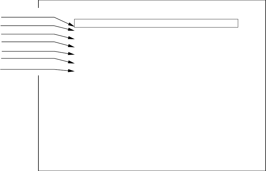
This preset allows you to change the priority of the NMEA data being read by the radar. Lat/Long,
Heading, Speed, Waypoint, Depth, Cross track error, and Magnetic compass deviation can be
adjusted so as to read the various NMEA sentences available for each in a prioritized format.
The highlighted NMEA sentence ID will become the priority sentence. To highlight a sentence ID,
scroll the cursor touch pad to required data (up or down) to bring border to that function. Then
scroll the cursor touch pad to right until the required sentence ID is selected. Then, rotate control
knob counter-clockwise until highlighted sentence ID is at the beginning of the list.
5.5.4.6.5 Initial adjustment settings (ADJUST)
The items in the ADJUST menu are done immediately following installation. They need not be
changed during normal operation.
(1) Adjusting distance (TIMING ADJ)
This adjustment calibrates the distance displayed on the radar screen to the actual distance.
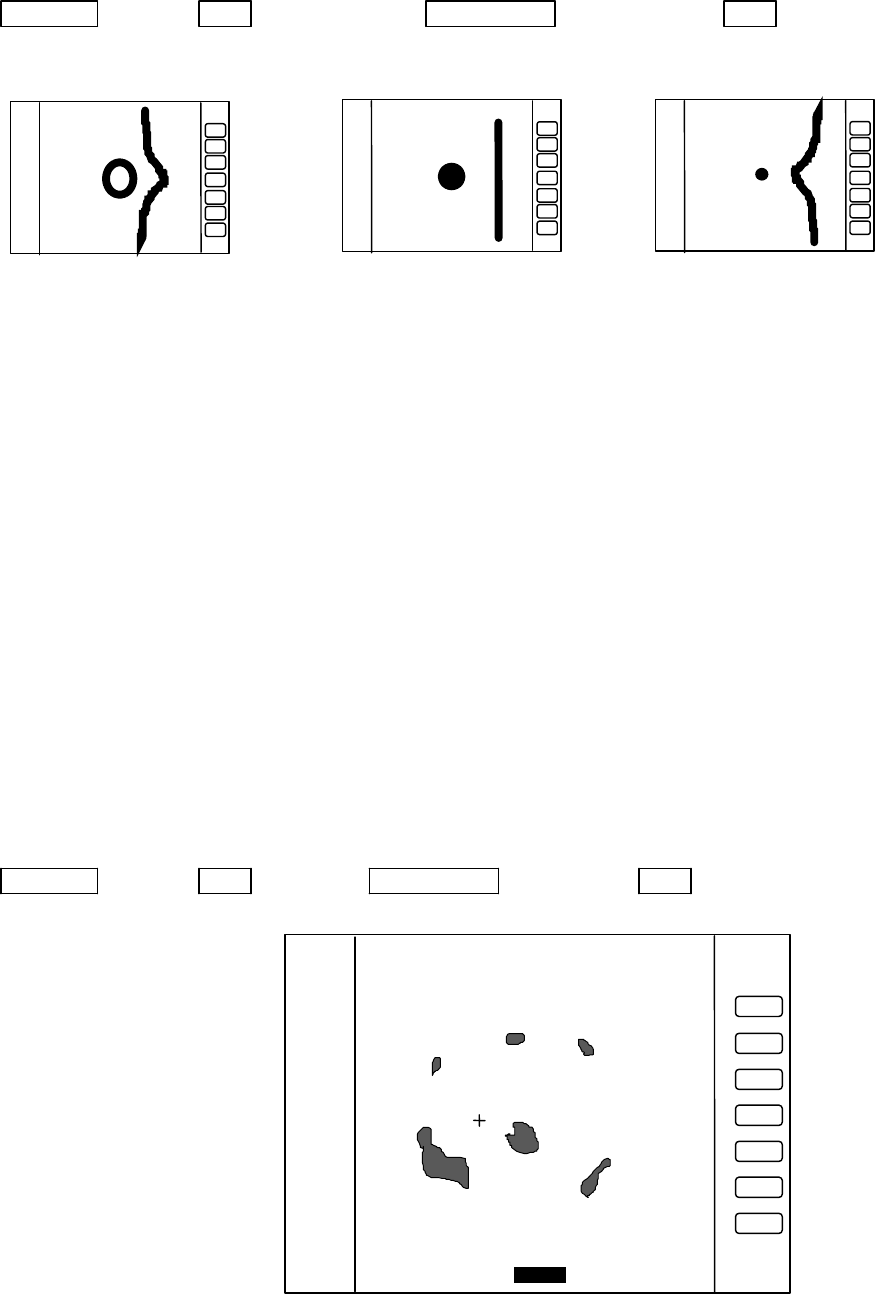
(1) First, set the radar range to 0.25 NM, FTC to minimum, and GAIN to optimum. Then adjust
STC until the pulse generated by the radar at the center of the screen is a round dot.
(2) Adjusting the distance.
(2-1) Press the “MENU” key and select SETUP>CUSTOM>ADJUST>TIMING ADJUST. Press
“ENT”.
(2-2) “TIMING ADJUSTMENT” will be displayed at the bottom of the screen. Using the control
knob, adjust the timing until the center dot appears as shown in (b). If there is a linear
target such as a bridge or breakwater, adjust timing until the target appears straight on
the screen.
(2-3) When the adjustment is finished, press the "ENT" key to exit from the distance adjustment
screen.
NMEA PRESET
L/L GGA>GLL>RMA>RMC
HEAD HDT>HDG>VHW>HDM>HCC>VTG
SPEED VHW>VTG>RMA>RMC
WAY POINT BEC>BWC>BWR>BER>BPI>RMB
DEPTH DBT>DPT
XTE RMB>XTE
MAG VAR RMA>RMC>HDG>HVD>HVM
SET WITH CONTROL KNOB
PRESS ENTER KEY TO RETURN

RA51/52/53/54/55 INSTRUCTION MANUAL – 05 63
Up/Down → ENT → Control knob → ENT
To select TIMIG ADJ Do Timing adjustment Fix TX Timing Delay
(2) Adjusting angle (HEAD ADJ)
This adjustment calibrates the heading direction displayed on the screen to the actual direction of
the ship.
Note: Heading offset value for open antenna is different from that for a radome antenna.
(1) Find one small target within a 0.5 to 1.5 NM range off your bow and is both within visible
range and is clearly displayed on the radar screen.
(2) Measure the bearing of this target from the bow using a compass. Let it be θc.
(3) Measure the bearing of the target in head up (HU) mode using EBL. Let it be θr.
(4) Calculate the following:
θc - θr: if θc is greater than θr
360 - (θr - θc): if θr is greater than θc
This is the azimuth error of your radar at installation. If ?c and ?r are equal, no adjustment is
needed.
Adjustment method
(1) Press the “MENU” key and select SETUP>CUSTOM>ADJUST>HEAD ADJUST. Press
“ENT”.
(2) “HEAD DIRECTION ADJUSTMENT” will be displayed at the bottom of the screen. Using
the control knob, set the value to the azimuth error you have calculated above.
(3) When the adjustment is finished, press the "ENT" key to exit from the distance adjustment
screen.
Up/Down → ENT → Control knob → ENT
Select HEAD ADJ. Set a value to.
(3) Adjusting tuning circuit (TUNING CAL)
This will adjust the automatic tuning circuit to its best operating point
a) Too far
b) Correct
c) Too shrunk
HEAD DIRECTION ADJUSTMENT
ADJUST WITH CONTROL KNOB
PRESS ENTER KEY TO RETURN
_358.8 °_
HEADING Adjustment
3
1
HU

64 RA51/52/53/54/55 INSTRUCTION MANUAL – 05
Adjustment in AUTO mode:
This adjustment is made by changing the center frequency of the receiver's automatic frequency
control circuit (AFC). Response speed of the AFC is 0.5 seconds. In other words, for each detent
of the rotary knob, the center frequency changes after 0.5 seconds. It takes approximately 2.5
seconds for the antenna to make one turn (24 RPM = 0.4 RPS). This means that you can see a new
target every 2.5 seconds. When tuning, turn the knob slowly to obtain the best image. The AFC
is calibrated by this adjustment.
Adjustment in MANUAL mode:
This adjustment is made by changing the center frequency of tuning range in the manual tuning
circuit. Adjusting the manual tuning compensates for frequency deviation of the magnetron
relative to temperature and time. It's necessary to do this adjustment when the radar is first
installed and whenever the magnetron is replaced. Observe a close range and stable target echo,
then turn the knob slowly to obtain the best image. After this adjustment, the manual
adjustment indication on screen becomes 50 and this is the new tuning range center. Manual
tuning must be selected in the echo menu for making manual adjustment of tuning.
(1) Choose several stable video images in the 6 NM range or more and select the long pulse
setting. (menu>echo>S/L)
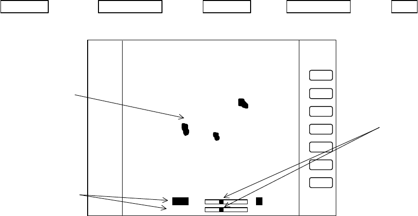
(2) Press the “MENU” key and select SETUP>CUSTOM>ADJUST>TUNING CAL. Press
“ENT”.
(3) “TUNING CALIBRATION” is displayed at the bottom of the screen. Select AUTO with the
up-down cursor key.
(4) While watching video images, adjust control knob until the maximum amount of echo returns
are displayed.
(5) Select MANUAL with the down cursor key.
(6) Adjust the control knob until echoes are clearly visible. This sets the middle value of manual
tuning.
(7) When the adjustment is finished, press the "ENT" key to exit from the TUNING
CALIBRATION screen.
Up/Down → Control knob → Up/Down → Control knob → ENT
Select AUTO Adjust tuning Select MANU Adjust tuning
(4) Adjusting antenna height (ANTENNA)
Depending on the height at which the antenna is installed, it may be necessary to make the
following correction.
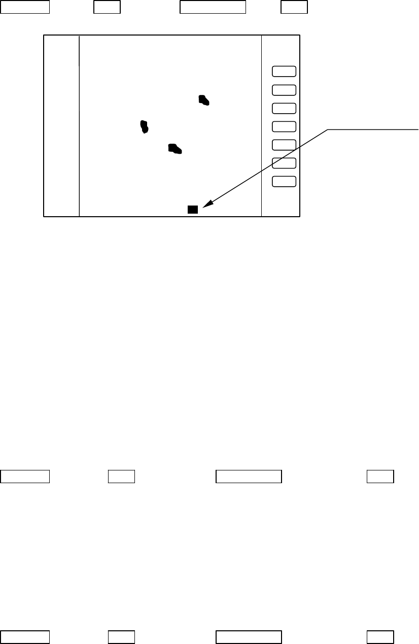
(1) Press the “MENU” key and select SETUP>CUSTOM>ADJUST>ANTENNA. Press “ENT”.
(2) “STC CURVE ADJUSTMENT” will be displayed at the bottom of the screen. Using the
control knob, choose a desired value from 1 to 9.
(3) Press the "ENT" key to exit from the adjusting antenna height screen
Adjust with control knob
Select with up-down
cursor key
Echo
remains.
TUNING CALIBRATION
READ OPERATION MANUAL
SELECT ITEM WITH ?? KEY
TUNE WITH CONTROL KNOB
PRESS ENTER KEY TO MEMORY
AUTO 31313131
MANUAL 36
3
1
HU

RA51/52/53/54/55 INSTRUCTION MANUAL – 05 65
Up/Down → ENT → Control knob → ENT
Select ANTENNA Choose value Complete
Echoes in short range are varied in accordance with antenna height. Use 9 for the lowest antenna
and 1 for the highest antenna. Actual adjustment of the ANTENNA HEIGHT is done by obtaining
a continuous echo return of sea clutter out to maximum selected range. Note that erasing sea
clutter in short-range functions will erase small targets as well.
(5) Setting automatic GAIN circuit (GAIN)
Adjustment in AUTO mode:
Set the radar to the 1.5 NM range. Press the "AUTO" button until AT2 appears at the left of the
screen. The G, S, and F readings below it should all have AT next to them, meaning they are all
set to the auto mode. This adjustment must be done after adjusting the Auto STC. Relative sizes
of targets that are processed remain at a constant level. The target signal of the auto gain circuit
is adjusted constantly, even if actual returns are varied due to a change of sea conditions. This
adjustment is made on a long-range scale, and should be adjusted to obtain a small amount of
noise on the display.
(1) Press the “MENU” key and select SETUP>CUSTOM>ADJUST>GAIN ADJ. Press “ENT”.
(2) “AUTO GAIN ADJUSTMENT” will be displayed at the bottom of the screen. Using the
control knob, choose a desired value from 1 to 30.
(3) Press the "ENT" key to exit from the adjusting screen.
Up/Down → ENT → Control knob → ENT
Select GAIN ADJ Choose value Complete
Adjustment in MANUAL mode:
Set the radar to the 1.5 NM range. Press the "STC" button to set the manual control mode. The
G, S, and F readings below it should all have values next to them, meaning they are all set to the
manual mode. Set G 60 (Gain 60), S 0 (STC 0) and F 0 (FTC 0) first. Then, enter to the
adjustment screen. This adjustment is made on a long-range scale, and should be adjusted to
obtain a small amount of noise on the display.
(1) Press the “MENU” key and select SETUP>CUSTOM>ADJUST>GAIN ADJ. Press “ENT”.
(2) “MANUAL GAIN ADJUSTMENT” will be displayed at the bottom of the screen. Using the
control knob, choose a desired value from 1 to 30.
(3) Press the "ENT" key to exit from the adjusting screen.
Up/Down → ENT → Control knob → ENT
Select GAIN ADJ Choose value Complete
(6) Setting automatic STC circuit (STC)
Adjustment in AUTO mode:
Set the radar to the 1.5 NM range. Press the "AUTO" button until AT2 appears at the left of the
screen. The G, S, and F readings below it should all have AT next to them, meaning they are all
set to the auto mode. AUTO STC will automatically delete echoes within 0.1 NM of your boat.
STC CURVE ADJUSTMENT
ADJUST WITH CONTROL KNOB
PRESS ENTER KEY TO MEMORY
STC CURVE _5_
3
1
HU
ANTENNA Adjustment
Adjust with Control knob

66 RA51/52/53/54/55 INSTRUCTION MANUAL – 05
Because the 0.1 N.M. detection zone provides data for the STC circuit outside the 0.1 N.M. range,
it's not recommended to make this adjustment close to shore or in a harbor area.
(1) Press the “MENU” key and select SETUP>CUSTOM>ADJUST> STC ADJ. Press “ENT”.
(2) “AUTO STC ADJUSTMENT” will be displayed at the bottom of the screen. Using the control
knob, choose a desired value from 1 to 16.
(3) Press the "ENT" key to exit from the adjusting screen.
Up/Down → ENT → Control knob → ENT
Select STC ADJ Choose value Complete
Adjustment in MANUAL mode:
Set the radar to the 1.5 NM range. Press the "STC" to set the manual control mode. The G, S, and
F readings below it should all have values next to them, meaning they are all set to the manual
mode. Set G 60 (Gain 60), S 60 (STC 60) and F 0 (FTC 0) first. Then enter to the adjustment
screen.
(1) Press the “MENU” key and select SETUP>CUSTOM>ADJUST> STC ADJ. Press “ENT”.
(2) “MANUAL STC ADJUSTMENT” will be displayed at the bottom of the screen. Using the
control knob, choose a desired value from 1 to 16.
(3) Press the "ENT" key to exit from the adjusting screen.
Up/Down → ENT → Control knob → ENT
Select STC ADJ Choose value Complete
(7) Setting HARBOR STC circuit (HARBOR)
Set 1.5N.M range, HBR, G AT (Gain Auto), S HB (STC harbor), F 0 (FTC 0) first.
This adjustment must be carried out after adjustment of auto gain. Harbor mode means that a
fixed STC depth is applied when the ship is going into a harbor or close to shore. This adjustment
will provide good short-range target detection.
(1) Press the “MENU” key and select SETUP>CUSTOM>ADJUST>STC ADJ. Press “ENT”.
(2) “HARBOR STC ADJUSTMENT” will be displayed at the bottom of the screen. Using the
control knob, choose a desired value from 1 to 16.
(3) Press the "ENT" key to exit from the adjusting screen.
Up/Down → ENT → Control knob → ENT
Select STC ADJ Choose value Complete