Koden Electronics RB719A Marine Radar RA55 User Manual C17 CHAP6 Mainte 1
Koden Electronics Co., Ltd Marine Radar RA55 C17 CHAP6 Mainte 1
Contents
C17
RA51/52/53/54/55 INSTRUCTION MANUAL – 05 67
CHAPTER 6. MAINTENANCE AND INSPECTION
There are high voltage circuits inside this radar. Do not attempt to open
the rear cover of display unit or disassemble internal parts. Leave this
to qualified service personnel. When you open the radome, power must
be off. Never work on or near the radome while it is operating.
Even if the power switch is OFF, this radar still has electrically charged
components inside.
Tab. 6-1 Owner Inspection and Maintenance Items
Replaceable items:
(1) Magnetron
This component is located in the scanner. If distant echo images have become less
visible, the magnetron probably is degraded. Contact your dealer or authorized repair
center for this service
Period of the replacement: 3000hour(typical) (500hour guarantee)
(2) LCD backlight
If the display screen becomes extremely dark and its illumination cannot be increased
by adjusting the Brilliance control, the LCD backlight may be faulty. Contact your
dealer or authorized repair center for this service
Period of the replacement: 15000hour(typical) (1000hour at 0 °C)
Interval Item Procedure
3-6 months Scanner hardware Check if the scanner’s mounting bolts are cor-
roded or loose.
LCD display Clean filter and LCD screen surfaces with a soft
moist cloth.
6-12 months Antenna drive Apply an even coating of grease to the entire
surface of the antenna drive gear. Be certain to
use grease that will not harm plastic surfaces.
Electrical connectors
Check electrical connectors on back panel of dis-
play unit for proper contact by unscrewing them
and examining the contacts. Remove any corro-
sion by polishing or using a contact cleaning
agent.
Antenna motor
brushes (open array
antennas)
Check length of brushes and replace if under
6mm.
!
WARNING
68 RA51/52/53/54/55 INSTRUCTION MANUAL – 05
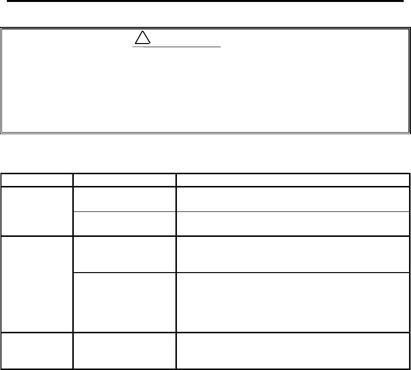
(3) Fuse
The fuse is built in the power
supply cable.
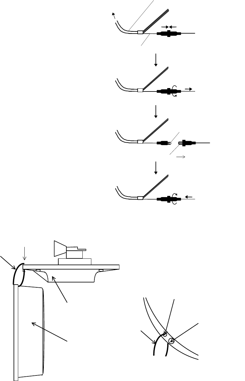
When working on the scanner, you can hang the upper half of the radome using a piece
of wire or cord through holes to either side of the mounting screws.
Push
Power supply cable
Wire(White)
Turn counterclockwise and
pull
Fuse
Spring
Push and turn
clockwise
Replace
new fuse
To display unit
Fixing screw
Hole
A: Top view
Cord
Cord
A
Radome(Upper)
Radome(bottom)