Koden Electronics RB719A Marine Radar RA55 User Manual C3 Chap2
Koden Electronics Co., Ltd Marine Radar RA55 C3 Chap2
Contents
C3
2 RA51/52/53/54/55 INSTRUCTION MANUAL – 05
CHAPTER 2. USING RADAR FOR
THE FIRST TIME
This chapter covers basic information and technical terms about radar for those who are using one
for the first time.
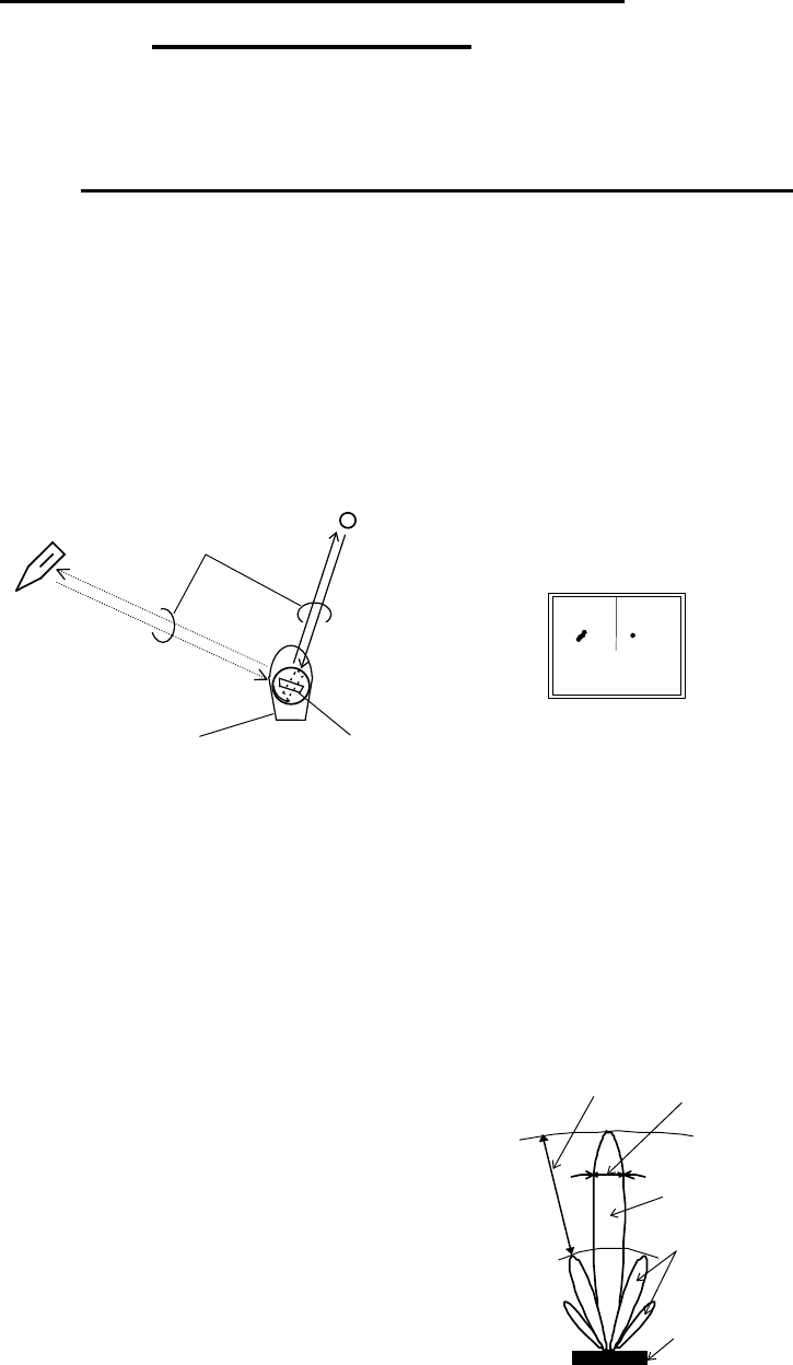
2.1 What is radar?
RAdio Detecting And Ranging
The word "radar" is an acronym for "RAdio Detecting And Ranging." In very simple terms, this is
how it works. A radio transmitter sends a quick microwave pulse, and then a receiver listens for
that signal's echo when it is bounced back from something in its path. The returning signal is
processed by a computer to determine its relative distance, position and bearing. This information
is graphically displayed on a screen for you to see. Other boats or ships, navigational markers,
landmasses and such are referred to as targets.
By knowing how long it takes for a signal to return, the distance to a target can be determined. As
the radar antenna scans through a 360-degree rotation, it can show where the target is relative to
your position. By repeated scans, you can see which direction another vessel is moving.
Fig.2-1 What is radar?
Antenna
How radar will perform is largely determined by its antenna or scanner. Increasing the size of the
antenna improves long-range performance and target discrimination, or the ability to distinguish
two separate targets at a distance. The critical factors are the antenna's beam width and side lobe
level. Typically, a radar antenna will radiate a tightly focused beam from the front of the array.
The longer the antenna array is, the narrower the beam width will be. Additionally, it will also
emit smaller amounts of energy to each side. The lower the side lobe level, the less the effect of a
false echo. The RA51 radars are equipped with a closed dome scanner, the RA52/53/54/55 has a
larger, open array.
Side lobe
The beam in which the strongest radio signal is radiated from
the antenna is called the “main lobe”. Those beams that are
radiated in other directions are referred to as the “side lobes”.
The side lobe level refers to the difference in level (signal
strength) between the largest side lobe and the main lobe.
Fig.2-2 Antenna pattern
Buoy
Other ship
Radar wave
Your ship
Antenna
Radar display
Beam width
Side lobe
level
Main beam
Side lobe
Antenna
RA51/52/53/54/55 INSTRUCTION MANUAL – 05 3
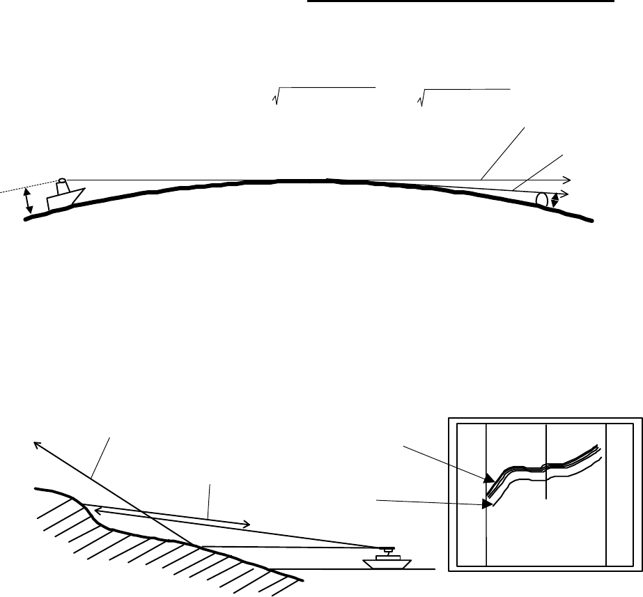
2.2 Characteristics of Radar Wave
Radio waves travel out from the antenna while bending slightly along the earth's surface. The
amount they bend depends on atmospheric conditions. The sight distance of a radar generally is
about 6% longer than the optical sight distance and is calculated using this equation:
Radar sight distance (NM) = 2.22 ( antenna height (m) + target height (m))
Fig.2-3 Radar wave
Targets difficult to display on screen
The intensity of the reflected radio signal from a target depends on the distance, height, and size of
the target, as well as its material and shape, along with the radar’s transmitter power output and
antenna size. Targets made of fiberglass, wood, or other low-reflectance materials or those that
have a small incident angle are difficult to display on a screen. Sandy beaches, and sandy or
muddy shallows can be difficult to catch. Because there's not much to reflect a signal back to you, a
coastline can actually be closer to your boat than it appears on the screen.
Fig.2-4 Targets difficult to display on screen
Shadow zones of radar
Radar waves propagate in a straight line. A high outcropping of land or a large ship will create a
shadow zone behind it and prevent you from seeing targets on the other side. More importantly, if
a mast or some part of the boat's superstructure is in the path of the antenna's sweep, this will also
create a shadow zone. No targets will be recognized behind it and it could create a dangerous
situation.
False echoes
Sometimes radar will display targets on screen that do not exist in the real world. You should be
aware of how and why this happens.
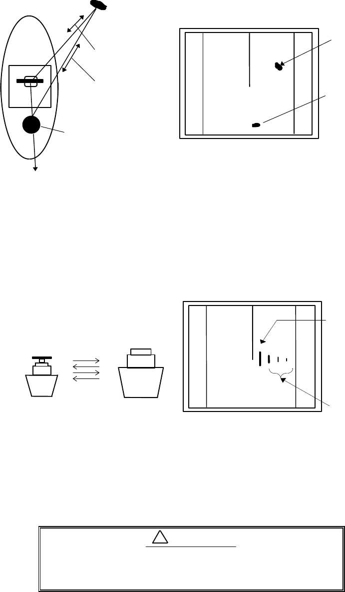
A. Ghost echoes
Sometimes one large object very near your boat will appear as two different targets onscreen. One
is the actual radar echo. The other is a ghost echo generated by a re-reflection of the original
signal. It comes back to your own boat, bounces back to the target, and then is picked up by the
h1
h2
Line of sight
Radar Radio
Wave
Earth
Apparent coastline
Actual(invisible)
coastline
Invisible
Visible
3
1
HU
4 RA51/52/53/54/55 INSTRUCTION MANUAL – 05
antenna on the second bounce. The actual echo appears at the correct distance and bearing on the
screen. The ghost echo appears somewhere behind your boat. This type of false echo is also gen-
erated by re-reflection of waves from bridges, quay walls or building along shore.
Fig.2-5 False echoes of radar (Ghost echoes)
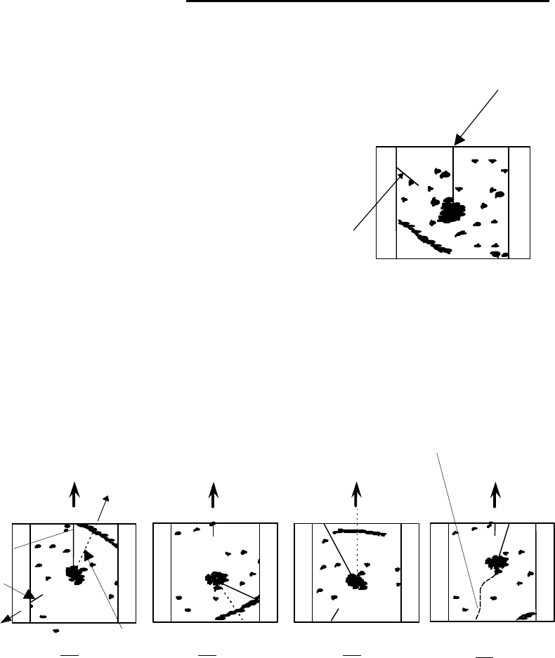
B. Multiple echoes
If there is a large vertical reflecting surface near your boat, as in the case when you pass alongside
a large ship, radar signals are repeatedly bounced back and forth between your boat and the other
object. Two to four images appear on the screen at equal intervals in the same bearing. This is
called a multiple echo. The image appearing closest to you is the real echo. Multiple echoes will
disappear as you move away from the reflecting object or its bearing changes.
Fig.2-6 False echoes of radar (Multiple echoes)
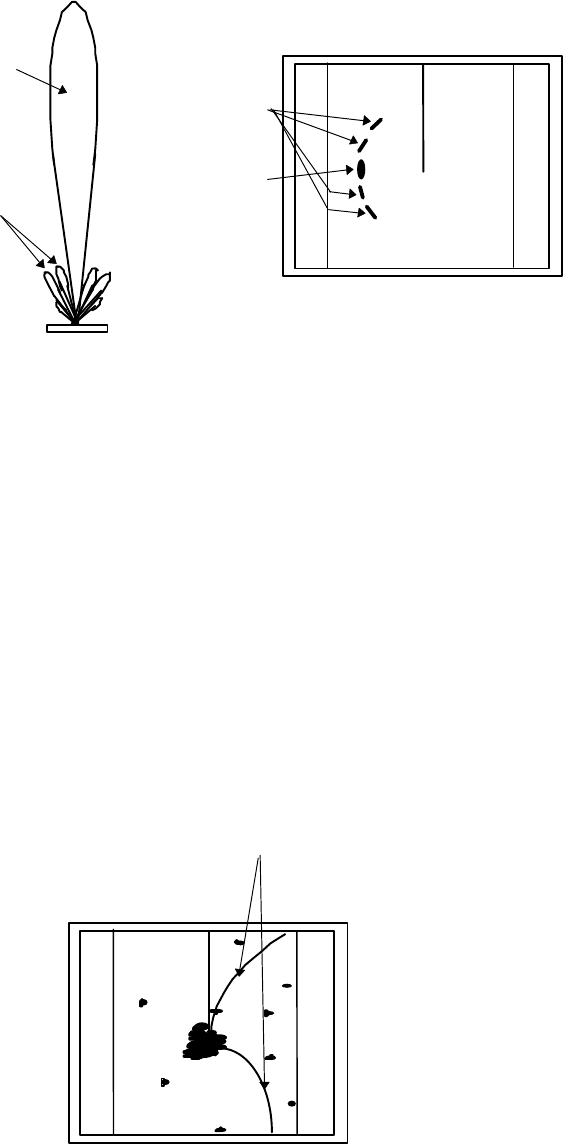
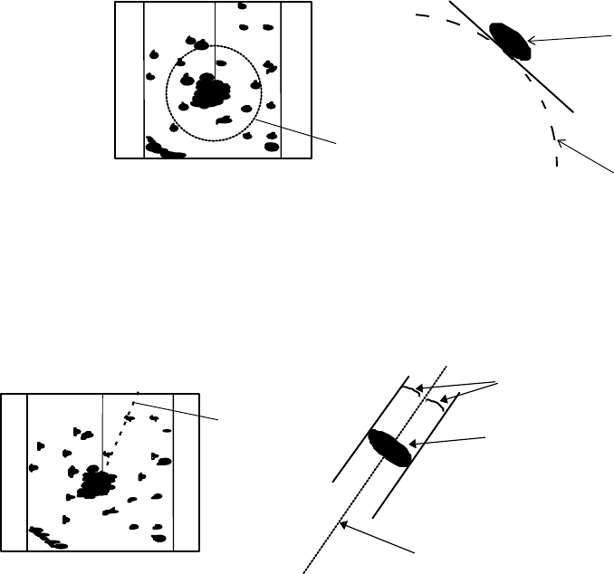
C. False echoes caused by side lobe
An antenna's side lobe emissions are low power, and will not register distant targets. However, if
there is a strong reflecting target near your boat, it sometimes may appear as a circular-arc false
echo on the screen.
When near large targets or land, your boat's mast
may sometimes appear as a circular-arc shaped
false echo.
CAUTION
!
Target
Direct reflection
path
Secondary
reflection path
Mast etc.
Real echo
Ghost echo
Direction of ghost echo
3
1
HU
3
1
HU Real echo
Multiple
echoes
RA51/52/53/54/55 INSTRUCTION MANUAL – 05 5
Fig.2-7 False echoes of radar (Caused by side lobe)
D. Distant false echoes caused by duct phenomenon
The duct phenomenon sometimes occurs when meteorological conditions create a temperature
inversion between layers of air. When this happens, radar waves propagate erratically and can
reach a location considerably farther away from your boat than the radar's maximum distance
range. What appears onscreen is a false echo that looks to be nearer than the actual target. Since
the true echo from the distant target is outside the measurement capabilities of the radar, its ap-
parent distance will change when you change ranges, and you can conclude that it's a false echo.
Radar interference
If another boat's radar is operating on the same frequency as yours, it can create interference on
your display. The interference usually appears as spiral or radial patterns. The RA51/52/53/54/55
radar has two levels of interference rejection control to eliminate interference. Turn it on to re-
duce or eliminate the interference.
Fig.2-8 Radar interference
3
1
HU
Antenna
Main beam
Side lobes
Real echo
False sidelobe
echoes
3
1
HU
Radar inrterference
6 RA51/52/53/54/55 INSTRUCTION MANUAL – 05
2.3 Terms Specific to Radar
HM (Heading Marker)
This is a line-shaped marker used to indicate the forward direction
of your boat.
North Mark
The marker to indicate the direction North is a short line ap-
proximately 1/6 of the screen size. It only appears when the radar is
connected to a suitable heading source provided through NMEA,
10/12 bit serial or sin/cos.
Fig.2-9 Heading Marker and North Mark
Display modes five (+HS)
The RA51/52/53/54/55 has four display modes. Each refers to the top of the screen as it relates to
the direction of your boat's travel.
Fig.2-10 Display modes
Head Up (HU)
The heads up mode corresponds with your current heading and shows what's directly in front of
you at the top of the screen. It gives you the position of other targets around you relative to your
boat.
North Up (NU)
In this mode, North is at the top of the screen. This allows you to compare your position with a
chart as you navigate. Heading data input is required for this mode to function.
Course Up (CU)
This is similar to North up except that your boat's destination is at the top of the screen. A straight
line from the bottom to top of the screen is your course bearing.
0.75
0.25
HU
HM(Heading Marker)
North Mark
Ship's
Heading
North
Scheduled
course
HM
EBL
North
mark
HU
NU
CU
TM
Ship's locus
(not displayed on screen)
North North Scheduled
course
0.75 0.75 0.75
0.25
TM
0.25
CU
0.25
NU
0.25
HU
0.75
RA51/52/53/54/55 INSTRUCTION MANUAL – 05 7
True Motion (TM)
In this mode, the boat icon is displayed as if it is moving on a marine chart while targets such as
islands and seashores are fixed in position. When the icon reaches a certain position on the screen
(approx. 2/3 of screen size), it is placed back on the opposite side on the screen. North is at the top
of the screen. External heading and speed data are needed for this mode.
VRM (Variable Range Marker)
This adjustable circular-shaped marker can be used to determine the distance of a target from your
boat. When measuring be certain to move the VRM to a point close to the center of the echo image
on the screen.
Fig.2-11 VRM
EBL (Electronic Bearing Line)
This straight-line marker can be rotated in any direction centered on your boat's position. Use the
EBL to indicate the advancing direction of your boat and its relative angle with a target.
Fig.2-12 EBL
VRM
Echo
0.75
0.25
HU
VRM
0.75
0.25
HU EBL
Echo
EBL
Equal intervals
8 RA51/52/53/54/55 INSTRUCTION MANUAL – 05
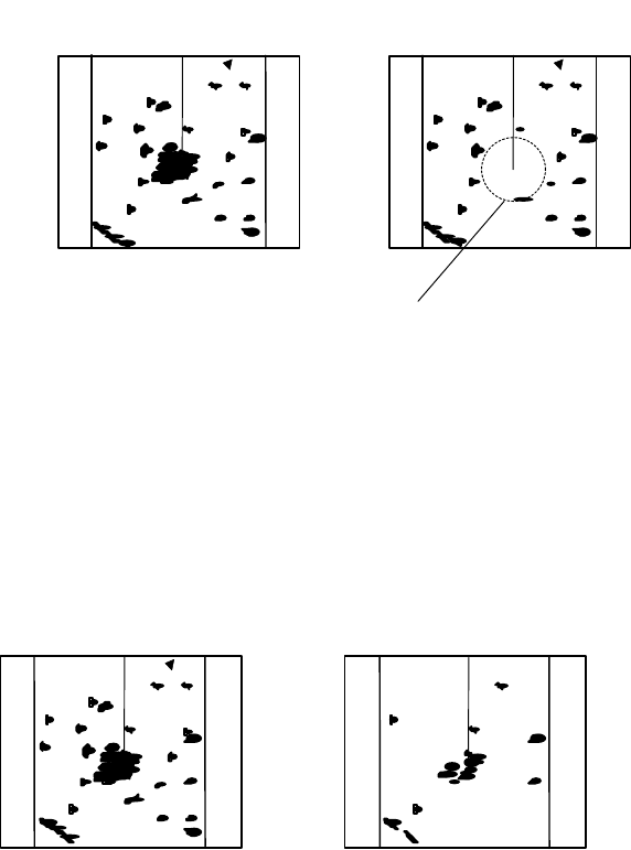
STC (Sensitivity Time Control)
Since echo signals received by the radar are stronger when they are coming from a short distance,
it's difficult to compare signal strength between each reflected signal. To overcome this, signal
strength is adjusted in such a way that the received signal levels coming from a short distance are
lowered. This is helpful when there are large reflected waves from sea surfaces during rough
weather.
Fig.2-13 STC
FTC (Fast Time Constant)
When it rains or snows, fine noise may appear over the entire screen, making it difficult to identify
echoes. In such a case, echo images on the screen can be made easily distinguishable by adjusting
FTC.
Fig.2-14 FTC
PPI (Plan Position Indicator)
A display system of radar. Reflected radar signal is displayed in plan.
0.75
0.25
HU
STC OFF
STC ON
0.75
0.25
HU
Echo is suppressed
around center
0.75
0.25
HU
FTC OFF
FTC ON
0.75
0.25
HU
Small noises
are reduced.