Koden Electronics RB719A Marine Radar RA55 User Manual C9 5 1Menu 1
Koden Electronics Co., Ltd Marine Radar RA55 C9 5 1Menu 1
Contents
C9
38 RA51/52/53/54/55 INSTRUCTION MANUAL – 05
5.5 MENU Operation ___________________________________________
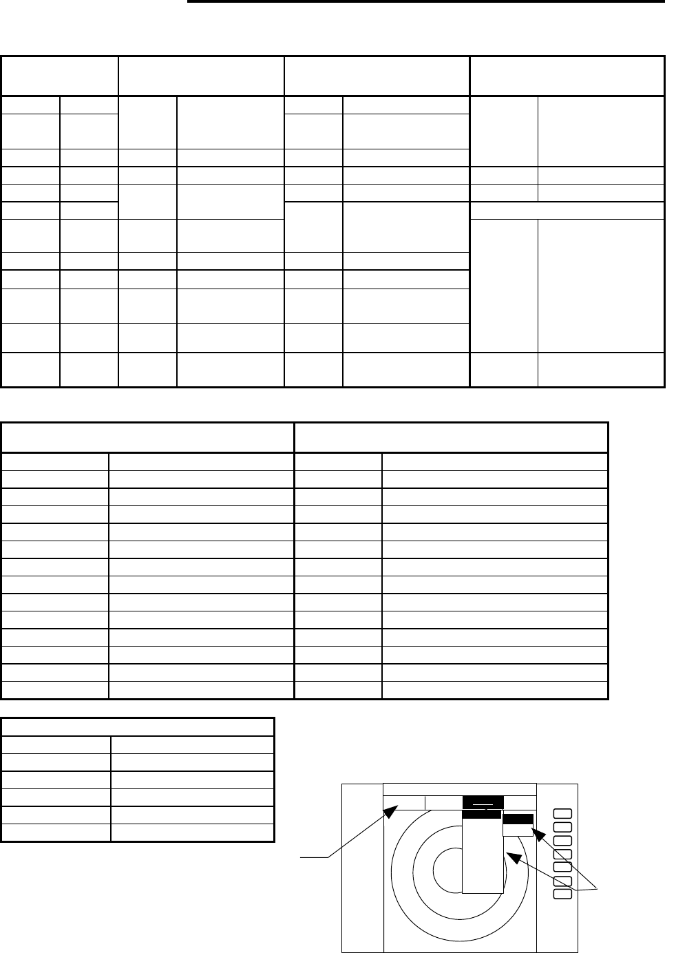
List of MENU
List of Main Menu
MARK
(MAIN-MENU)
NAV
(MAIN-MENU) ECHO
(MAIN-MENU) SETUP
(MAIN-MENU)
EBL1 ON OFF
GAIN AUTO MANU
VRM1 ON OFF
MODE HU HS NU CU
TM STC AUTO MANU
HARBOR
EBL2 ON OFF
GZ ON OFF FTC AUTO MANU
WINDOW PPI SEMI3D/PPI
PPI/PPI PPI/NAV
ALLPPI ALL PPI/PPI
MOB
VRM2 ON OFF
OFF-C ON OFF TUNE AUTO MANU SEL WIN
FL EBL2
ON OFF
ST OFF ST1 ST2 PICTURE DAY NIGHT
FL VRM2
ON OFF
SLEEP OFF 5min 10min
15min
SYSTEM CHECK
HDG OFF
OFF ACQ (*1)
TRACK OFF 15SEC 30SEC
1MIN 3MIN 6MIN
CONT
///CSR ON OFF
DATA ON OFF (*1) ZOOM ON OFF
RINGS ON OFF
DEL (*1) SL SHORT LONG
VAR
RNG
ON OFF
TGT
NUM
(*1)
TARGET
ALL DEL
(*1)
CUSTOM KEY ASSIGNMENT
PRESET1
(SUB-MENU)
PRESET2
(SUB-MENU)
NMEA PRESET
ADJUST (SUB-MENU)
ATA PRESET (*1)
+MK
LINE
ON OFF
(*1): For ATA
List of Custom Menu
PRESET1 (SUB-MENU) PRESET2 (SUB-MENU)
HM FLSH ON OFF GZ LEVEL 1-7
STERN M ON OFF GZ MODE IN OUT
NORTH M ON OFF HOLD ON OFF
ST’BY NAVI NOR DISPLAY RDR MONI NAV
BUZ VOL OFF LOW HIGH EXT BUZ OFF CONT INT
RM UNIT NM KM SM IN P/R 1080 1024 2048 4096 360
DEPTH M FT FM OUT P/R 1080 1024 2048 4096 360
TEMP °C °F DEMO ON OFF
EBL BRG REL TRUE MAG IR OFF IR1 IR2
WP BRG TRUE MAG SPD SET NMEA MANU 0.0 KT LOG 200P
HEAD INPUT NMEA SIN/COS 12BIT 10BIT
LANGUAGE 16 countries
HEAD TRUE MAG SCAN SPEED
STD HIGH
+MK MODE DIST/BRG LAT/LON COLOR MONO MULTI
P TABLE 0 – 2
ADJUST (SUB-MENU)
TIMING ADJ
HEAD ADJ
TUNING CAL.
ANTENNA 1-9
GAIN 1-30
STC 1-16
+
ST’BY
.75
. 25
HU
STC >
FTC >
TUNE >
ST >
TRACK >
ZOOM >
S/L >
MARK
NAV
ECHO SETUP
ECHO
GAIN >
MANU
AUTO
MAIN-
MENU
SUB-MENU
RA51/52/53/54/55 INSTRUCTION MANUAL – 05 39
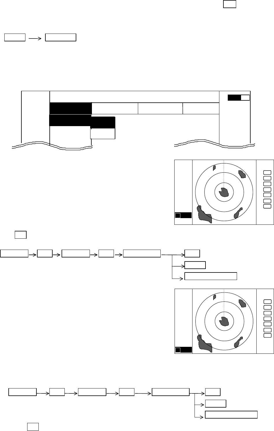
5.5.1 Mark Menu xxx = keys to press
Press the "MENU" key and select "MARK" from the four displayed menus by using the left or right
arrows on the cursor pad. The contents of the selected MENU will reveal beneath its name when
it's highlighted.
MENU Left/Right
(Select MARK)
5.5.1.1 Bearing measurement (EBL1)
(1) Select EBL1 from the pull-down display items using the up-down cursor key, and press the "ENT"
key.
(2) When the ON/OFF box is displayed beside the EBL1 item, select ON with the up-down cursor keys
and press the "ENT" key.
(3) When the "ENT" key is pressed, electronic bearing line
(EBL1) appears and the angle from the direction of the
boat's heading will appear in a highlighted display at the
lower left of the screen. The displayed EBL angle is
either relative to your heading, true or magnetic north,
depending on the setting of "EBL BRG" in the
"SETUP>CUSTOM>PRESET1" menu.
(4) Rotate the control knob until the line is at the center of
the target and read the bearing. Press "ENT" or another
function key and the EBL will remain onscreen. To
remove it, either use the menu or press the EBL1 soft key.
Note: 1 xxx.x indicates the relative bearing measured by EBL1.
Up/Down ENT Up/Down ENT Control knob ENT
(Select EBL1) (Select ON) (EBL1 operation) MENU
Other function key
5.5.1.2 Determining distance (VRM1)
(1) Select VRM1 from the pull-down display items using the
up-down cursor key and press "ENT" key.
(2) When the ON/OFF box is displayed beside the VRM1
item, select ON with the up-down cursor keys and press
the "ENT" key.
(3) When the "ENT" key is pressed, the variable range
marker1 (VRM1) appears and the distance from it to the
boat will appear in highlighted characters at the lower
left of the screen.
(4) Using the control knob, change the size of the ring until you place the marker on the front
edge of the target. Read the distance. Press "ENT" or another function key and the VRM
will remain onscreen. To remove it, either use the menu or press the VRM1 soft key.
Up/Down ENT Up/Down ENT Control knob ENT
(Select VRM1) (Select ON) (VRM1 operation) MENU
Other function key
Note: 1 xx.xx NM indicates VRM1.
MARK
EBL1
>
VRM1 >
EBL2 >
.75
.25
HU NAV ECHO SETUP
MARK
>>>
0.23NM
A
OFF
ON
. 75
.25
HU
+
1 0.0
°
.75
.25
HU
+
1 0.00NM
40 RA51/52/53/54/55 INSTRUCTION MANUAL – 05
5.5.1.3 Bearing measurement (EBL2)
Use the same procedure for placing EBL1. The angle measurement will appear in highlighted
characters at the lower right of the screen.
Note: 2 xxx.x indicates EBL2.
5.5.1.4 Determining distance (VRM2)
Use the same procedure for placing VRM1. The distance measurement will appear in highlighted
characters at the lower right of the screen.
Note: 2 xx.xx NM indicates VRM2.
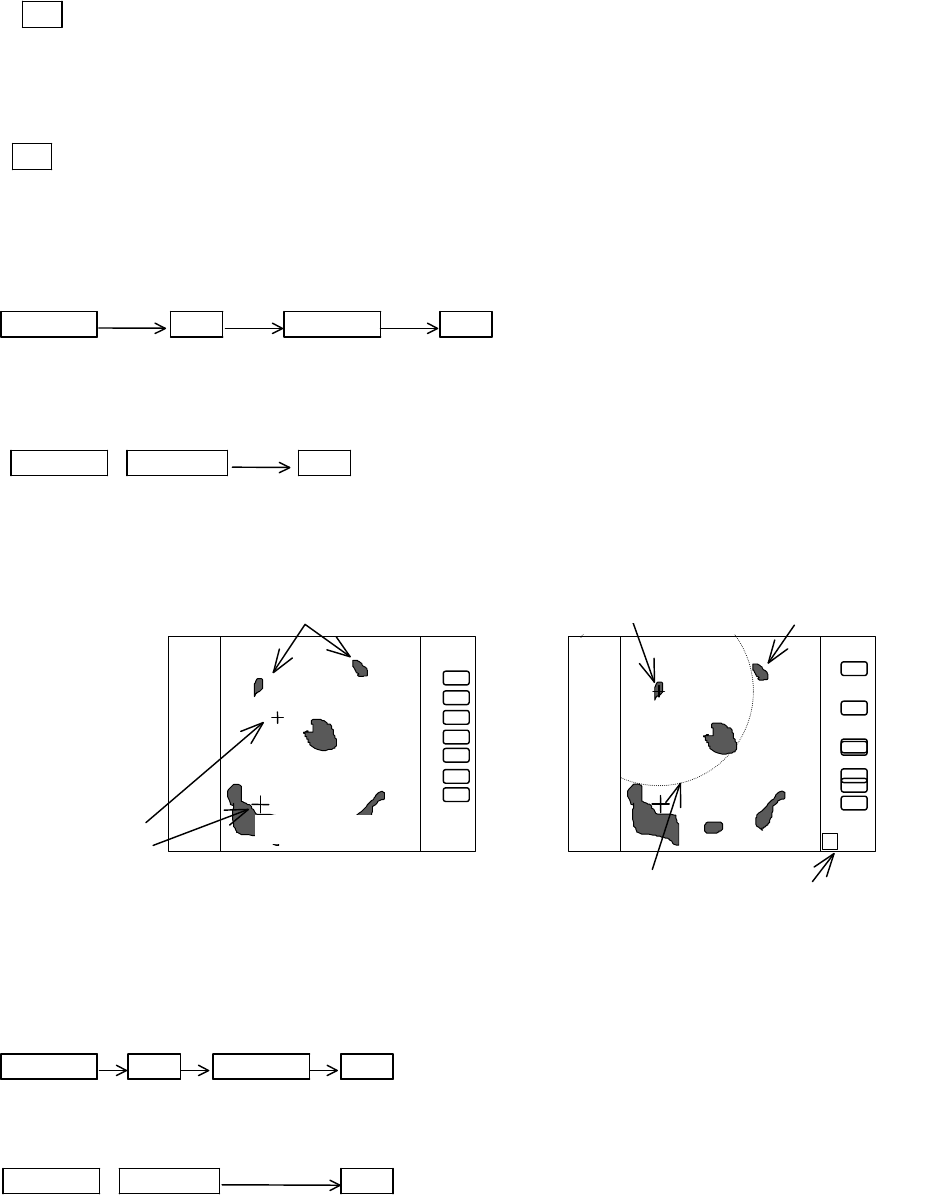
5.5.1.5 Measuring the distance between two points (VRM2, FL VRM2)
(1) Select FL VRM2 on the MARK menu and press the "ENT" key.
(2) Select ON from the ON/OFF box and press "ENT". “SET START POINT” is displayed and a
small cross mark appears.
Up/Down ENT Up/Down ENT ----------FL VRM2 is turned ON and the small cross
(Select FL VRM2) (Select ON) mark appears.
(3) Use the left-right and up-down cursor keys to place the cross mark on one of the two echoes
whose distance will be measured, and press the "ENT" key.
Up/Down &Left/Right ENT --------------------------------Criterion of the reference point is set.
(Place the cross cursor on an echo)
(4) Select VRM2 from the menu as described previously or press the "VRM2" soft key. Rotate the
control knob until it is on the second echo, then read the distance between the two echoes or
points in the highlighted text at the lower right of the screen
Note: FL VRM2 center do not follow to the "ZOOM" and "OFF-C" modes.
5.5.1.6 Measuring the angle between two points (EBL2, FL EBL2)
(1) Select FL EBL2 on the MARK menu and press the "ENT" key.
(2) Select ON from the ON/OFF box and press "ENT". “SET START POINT” is displayed and a
small cross mark appears.
Up/Down ENT Up/Down ENT --------- FL EBL2 is turned ON and the small cross mark appears.
(Select FL EBL2) (Select ON)
(3) Use the left-right and up-down cursor keys to place the small cross mark on one of the two
echoes whose angle will be measured, and press the "ENT" key.
Up/Down &Left/Right ENT ------ Criterion of the reference point is set.
(Place the cross cursor on an echo)
(
4) Select EBL2 from the menu as described previously or press the "EBL2" soft key. Rotate the
control knob until it is on the second echo, then read the angle in the highlighted text at the
lower right of the screen. The angle is relative to either the boat's heading, true or magnetic
north, depending on the setting of "EBL BRG" in the "SETUP>CUSTOM>PRESET1" menu.
.75
.25
HU
2 0.72NM
Place the VRM2 on other target
SET START POINT
.75
.25
HU
To measure the distance between two targets
Small cross mark
Cross mark
FL VRM2 Indication o
f VRM2
Center of VRM2
RA51/52/53/54/55 INSTRUCTION MANUAL – 05 41
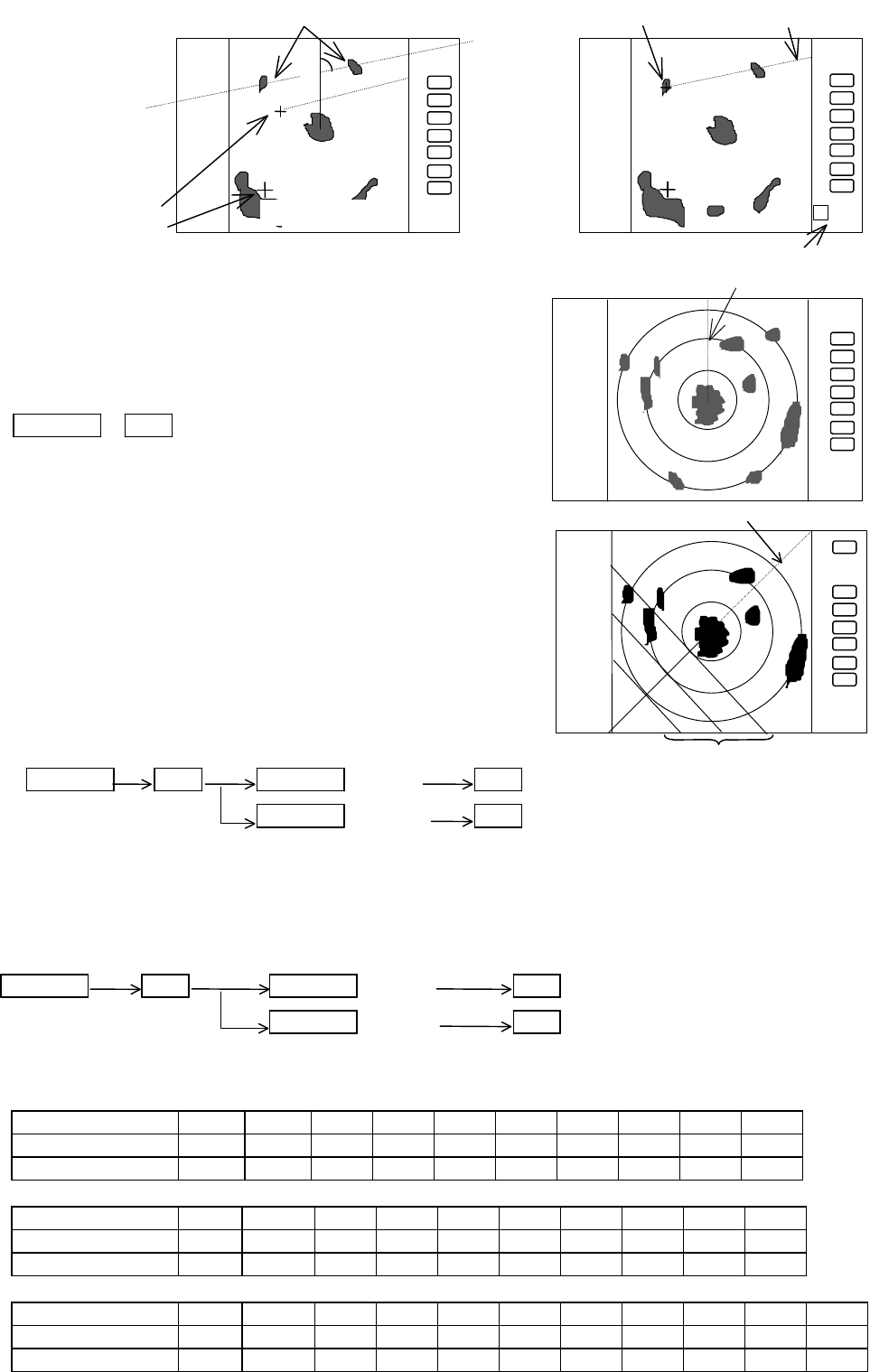
5.5.1.7 Erasing heading marker temporarily (HDG OFF)
(1) Use the up-down cursor key to select HDG OFF from
among the pulled down and displayed items.
(2) Press the “ENT” key. The heading marker is not
displayed as long as you hold down the "ENT" key.
Up/Down →ENT The heading marker is off as long as you press and
(Select HDG OFF) hold the “ENT” key down.
5.5.1.8 Using parallel cursor (///CSR)
Normally the EBL is used to measure the exact bearing
from the position of your boat to a target. However, you
can also use parallel cursors.
(1) Select ///CSR from the MARK menu, press "ENT" and
select ON.
(2) Press the “ENT” key. Parallel cursors will appear on
the screen. As you move the EBL, the parallel cursors
will also rotate.
(3) To cancel the ///CSR function, either select OFF in the
menu or press the ///CSR soft key.
Up/Down ENT Up/Down (Select ON) ENT Parallel cursor appears.
(Select ///CSR) Up/Down (Select OFF) ENT Parallel cursor disappears.
Note: Interval of ///CSR is same as fixed range marker. ///CSR moves with EBL1.
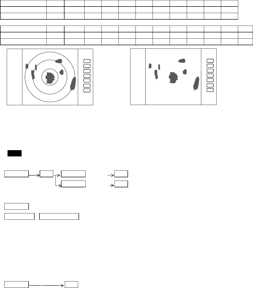
5.5.1.9 Establishment of the indication of the RANGE RINGS (RINGS)
(1) Select RINGS from MARK menu and press the “ENT” key.
(2) Use the up-down key to select ON or OFF and press the “ENT” key
Up/Down ENT Up/Down (Select ON) ENT ------------- Range rings appear.
(Select RINGS) Up/Down (Select OFF) ENT ------------- Range rings disappear.
Number of range rings and range interval
Radome antenna (RA51)
Range 0.125
0.25 0.5 0.75 1.5 3 6 12 24 36
Number of Rings 2 2 2 3 6 6 6 6 6 6
Interval 0.0625
0.125
0.25
0.25 0.25
0.5 1 2 4 6
Open antenna (RA52)
Range 0.125
0.25 0.5 0.75
1.5 3 6 12 24 48
Number of Rings 2 2 2 3 6 6 6 6 6 6
Interval 0.0625
0.125 0.25
0.25
0.25
0.5 1 2 4 8
Open antenna (RA53)
Range 0.125
0.25 0.5 0.75
1.5 3 6 12 24 48 64
Number of Rings 2 2 2 3 6 6 6 6 6 6 4
Interval 0.0625
0.125 0.25
0.25
0.25
0.5 1 2 4 8 16
.75
.25
HU
2 20.3°
FL EBL2
Origin of EBL2
Indication of EBL
SET START POINT
.75
.25
HU
Measure the angle between two points
Small cross mark
Cross mark
.75
.25
HU
Not displayed while ENT key is held
down.
.75
.25
HU
EBL1
Parallel cursor
42 RA51/52/53/54/55 INSTRUCTION MANUAL – 05
Open antenna (RA54)
Range 0.125
0.25 0.5 0.75
1.5 3 6 12 24 48 72
Number of Rings 2 2 2 3 6 6 6 6 6 6 6
Interval 0.0625
0.125 0.25
0.25
0.25
0.5 1 2 4 8 12
Open antenna (RA55)
Range 0.125
0.25 0.5 0.75
1.5 3 6 12 24 48 96 120
Number of Rings 2 2 2 3 6 6 6 6 6 6 6 6
Interval 0.0625
0.125 0.25
0.25
0.25
0.5 1 2 4 8 16 20
5.5.1.10 Variable range function (VAR RNG)
Using the "RANGE UP" and "RANGE DOWN" buttons changes the displayed range in small
predetermined increments. The VAR RNG function allows you to make the change in 0.1 NM
increments using the up and down arrows on the cursor pad.
(1) Select VAR RNG from the MARK menu press "ENT", then turn on the function.
(2) VAR will be displayed at the upper left of the screen beside MODE.
Setting procedure
Up/Down ENT Up/Down (Select ON) ENT -------VAR RNG function is turned ON
(Select VAR RNG) Up/Down (Select OFF) ENT -------VAR RNG function is turned OFF
Method of use
Up/Down ----------------------------------------------------------------Range changes continuously
RANGE UP &RANGE DOWN -----------------------------------Range changes in step
(3) To cancel the VAR RNG function, turn it off using the menu or press the "VAR RNG" soft key.
5.5.1.11 Output the position of the cursor location to another NMEA device (TARGET).
(1) Turn on the TARGET function in the MARK menu
(2) Using the cursor pad, move the cursor cross so it is directly over the position you would like to
send to another navigation unit.
(3) When you press "ENT" the latitude and longitude data of the position will be output to the
NMEA port in TLL format.
Up/Down ENT ----------------------------------Output the L/L position of the cursor
(Select TARGET)
Note: When you activate this function, nothing happens onscreen.
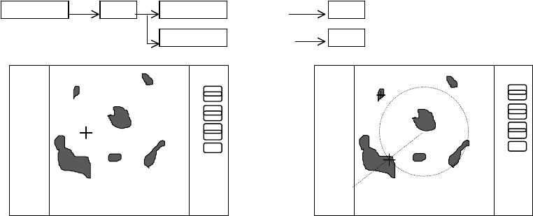
5.5.1.12 Determine the distance and bearing to a marker (+MK LINE).
(1) Select +MK LINE from the MARK menu and turn it on.
(2) A variable range marker and an electronic bearing line will appear onscreen. A cross marker
will be at their intersection. This is the mark position.
(3) The variable range marker and the electronic bearing line will follow the cross marker with
the Up/Down and Left/Right cursor pad control. Use them to place the cross marker over the
position to which you want to determine range and bearing.
(4) The data will be displayed in the lower left corner of the screen.
(5) Turn off the function using the menu or press the "+MK LINE" soft key.
.75
.25
HU
.75
.25
HU
Range rings ON
Range rings OFF
RA51/52/53/54/55 INSTRUCTION MANUAL – 05 43
Setting procedure
Up/Down ENT Up/Down (Select ON) ENT ---------------+MK LINE function is turned ON
(Select +MK LINE) Up/Down (Select OFF) ENT ---------------+MK LINE function is turned OFF
.75
.25
HU
.75
.25
HU
+MK POS
230.0°
0.47
+MK POS
230.0°
0.47
+MK LINE OFF
+MK LINE ON
The distance/bearing marker follows to cross
cursor. EBLs and VRMs can be used separately.