Koden Electronics RB719A Marine Radar RA55 User Manual C4 Chap3 01
Koden Electronics Co., Ltd Marine Radar RA55 C4 Chap3 01
Contents
C4
RA51/52/53/54/55 INSTRUCTION MANUAL – 05 9
CHAPTER 3. INSTALLATION
This chapter shows how to install the RA51/52/53/54/55 radar on your boat and the precau-
tions you'll need to observe.
3.1 Checking Inventory ___________________________________
Carefully unpack the box and check to see that all components are present.
RA51 RA52 RA53 RA54 R55
Item Q'TY Q'TY Q'TY Q'TY Q'TY
Display unit 1 (RF720A) 1 (RF720A) 1 (RF720A) 1 (RF720A) 1 (RF720B)
Scanner unit 1 (RB715A) 1 (RB716A) 1 (RB717A) 1 (RB718A) 1 (RF719A)
Display cover 1 1 1 1 1
Fuse 2 2 2 2 2
Interconnecting cable 1 (10 m) 1 (10 m) 1 (10 m) 1 (10 m) 1 (15 m)
Power supply cable 1 (2 m) 1 (2 m) 1 (2 m) 1 (2 m) 1 (2 m)
M10 hexagonal bolt 4 sets 0 0 0 0
M12 hexagonal bolt 0 4 sets 4 sets 4 sets 4 sets
Motor brush 0 2 2 2 2
Your unit was shipped with a 10m(or 15m) interconnecting cable. Longer or shorter cable is
also available as an option, as listed in Tab.3-1.
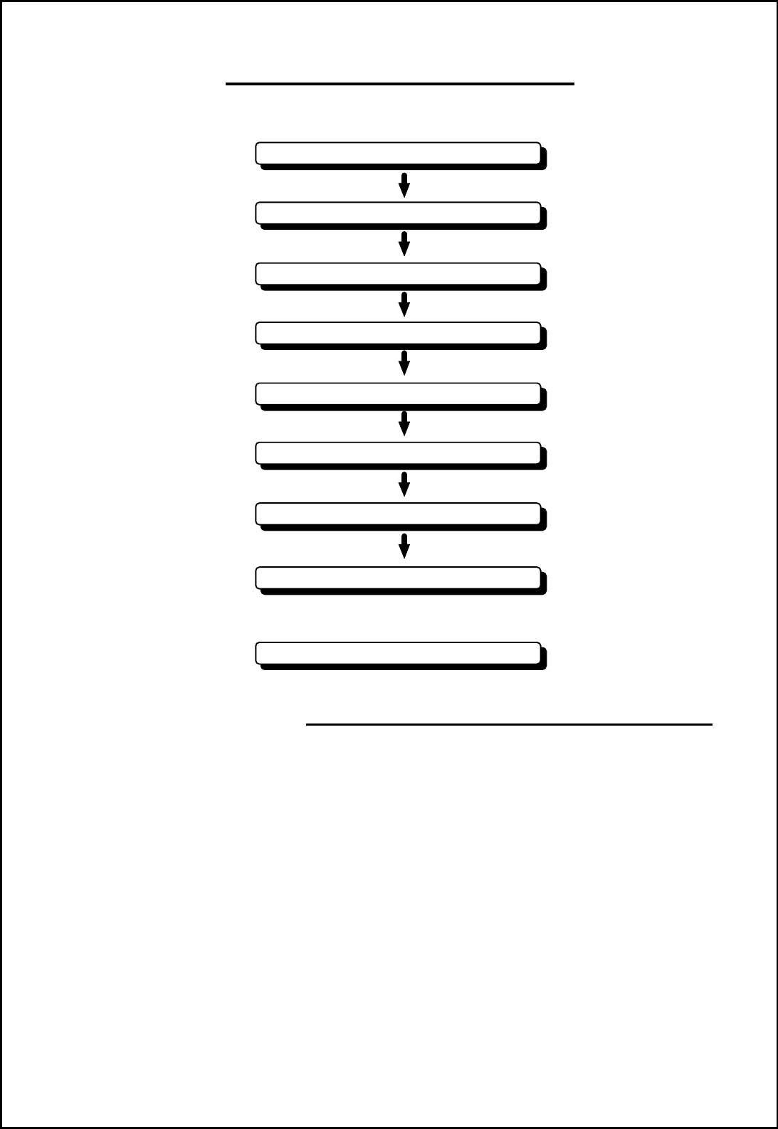
Checking contents of your package
Checking power supply voltage
Determining place of installation
Installing scanner unit
Installing display unit
Connecting cables
Adjustment
Connecting external equipment
When discarding Your radar
10 RA51/52/53/54/55 INSTRUCTION MANUAL – 05
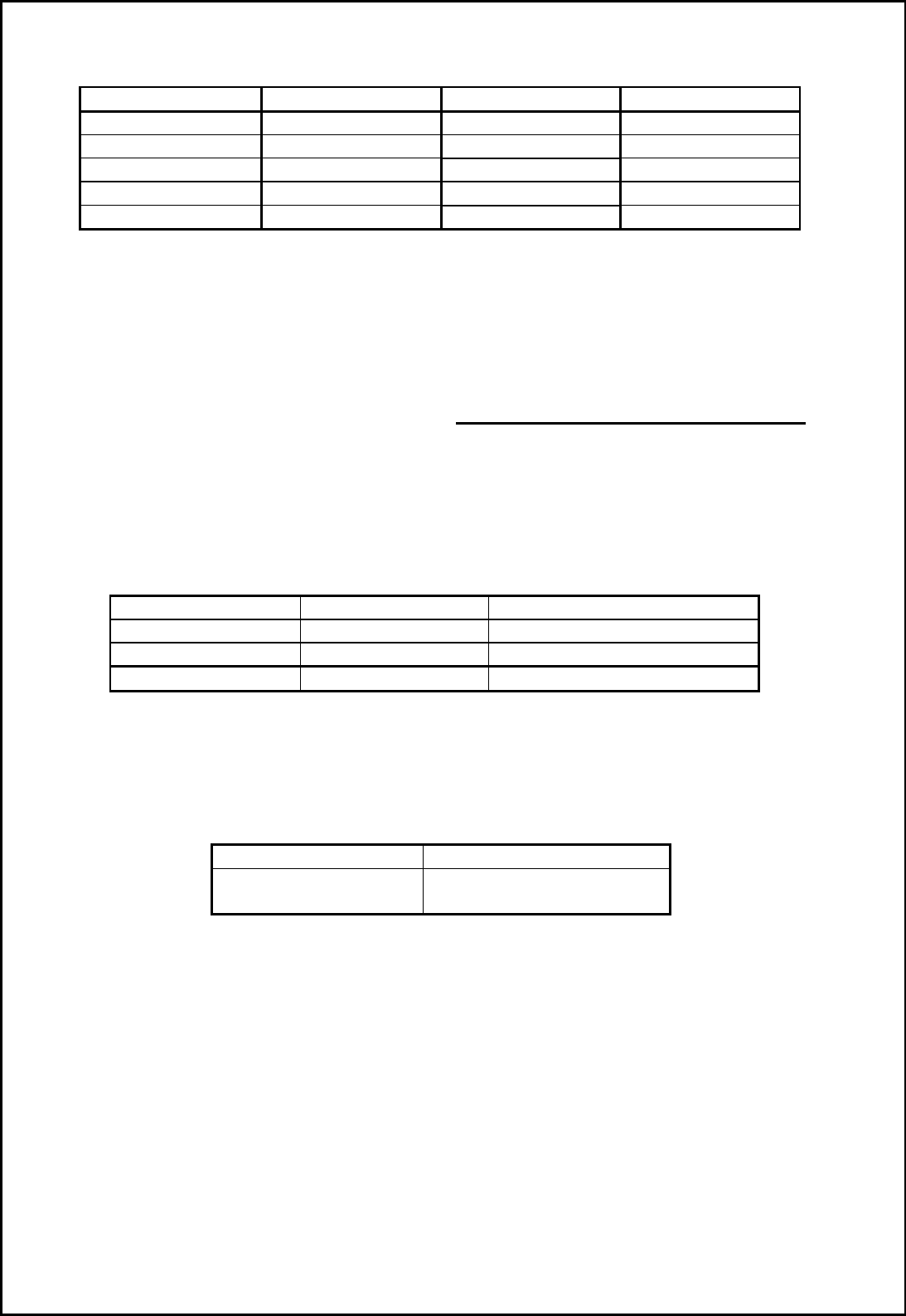
Tab.3-1 Optional Interconnecting Cable
You'll need to supply the following hardware:
Item QTY Remarks
Tapping screw or M5 bolt and nut 6 sets To install display unit
Grounding wire 1 Earth line for display unit
Grounding wire and crimp terminal 1 set Earth line for scanner unit
3.2 Checking Power Supply Voltage___________________________
3.2.1 Power Supply Requirements
Tab.3-2 shows the power requirements for the RA51/52/53/54/55 radar. If the unit is supplied
with less than the specified voltage, it won't operate properly. Keep in mind that when the
unit is initially powered on there will be a peak current surge. Check all circuits back to the
power source for correct wire gauge and tight connections.
Tab.3-2 Power Supply Requirements
*A.C. power cannot be used
3.2.2 Fuse Replacement
CAUTION: Use only exact replacements.
Tab.3-3 Supply Voltage vs. Fuse Ratings
Main Fuse Motor Fuse
15A/250V or 125V *
(6.3F x 32mm) T3.15A/250V or 125V
(5F x 20mm)
RA51 RA52/53/54 RA55
Cable length Product No. Product No. Product No.
10m(If you need) 242J158055A
15m 242J158055B 242J159098B
20m 242J158055C 242J159098C 242J159098C
30m 242J158055D 242J159098D 242J159098D
Supply voltage used
Maximum current
Allowable range of voltage
DC12V 14A 10.2-41.6V
DC24V 6A 10.2-41.6V
DC24V (for RA55) 15A 18.0-41.6V
RA51/52/53/54/55 INSTRUCTION MANUAL – 05 11
3.3 Where to Install the Scanner _____________________________
3.3.1 Scanner unit
Radar's target detection capacity varies greatly depending on the position of the scanner. An
ideal position is a location high above the ship's keel line where there is no obstacle all around
the scanner. In an actual ship, such an ideal location is limited by various factors. To comply
with FCC RF exposure requirements, the radar antenna for this scanner must be installed to
provide a separation distance of 1.3 m or more from all persons.
(a) Install the scanner as high as possible.
Consider the structural support of the location. Will it hold the weight of the scanner?
How difficult will it be to get to the scanner for maintenance?
(b) Install the scanner away from masts.
If the scanner is installed at the same height as a mast, radar waves may be blocked,
creating shadow zones or generating false echoes.
(c) Install the scanner forward of obstacles.
If you can't avoid an obstacle, place the scanner on the bow side of it. When installing the
scanner on a mast, position it in front of the mast. (If obstacles cannot be avoided for
structural reasons, refer to "Shifting away from obstacles" in Section 3.3.3.)
(d) Do not install the scanner near hot or heat-generating items.
Do not install the scanner where it may be subjected to smoke or hot air from exhausts or
heat from lights.
(e) Install the scanner away from other antennas.
Keep it as far as possible from the antennas of other electronic equipment.
Radar scanners will cause interference with radio
transceivers. Keep them as far apart as possible
(f) Keep the cable length as short as possible.
Keep the distance from the scanner to the display unit within the standard cable length of
10 m (or 15m). If you need a longer cable, limit the length to a maximum of 100 m.
3.3.2 Display unit
The display unit can be installed in a helm console, bulkhead, or electronics box. Consider
these suggestions:
(a) A place where you can see the boat's bow when looking straight up from the radar screen.
(b) A place where there is no direct sunlight to avoid display temperature buildup.
(c) A place where there is good ventilation and minimum vibration.
(d) A place where the display unit is more than the minimum safe distance from a magnetic
compass as listed in Tab.3-5 below.
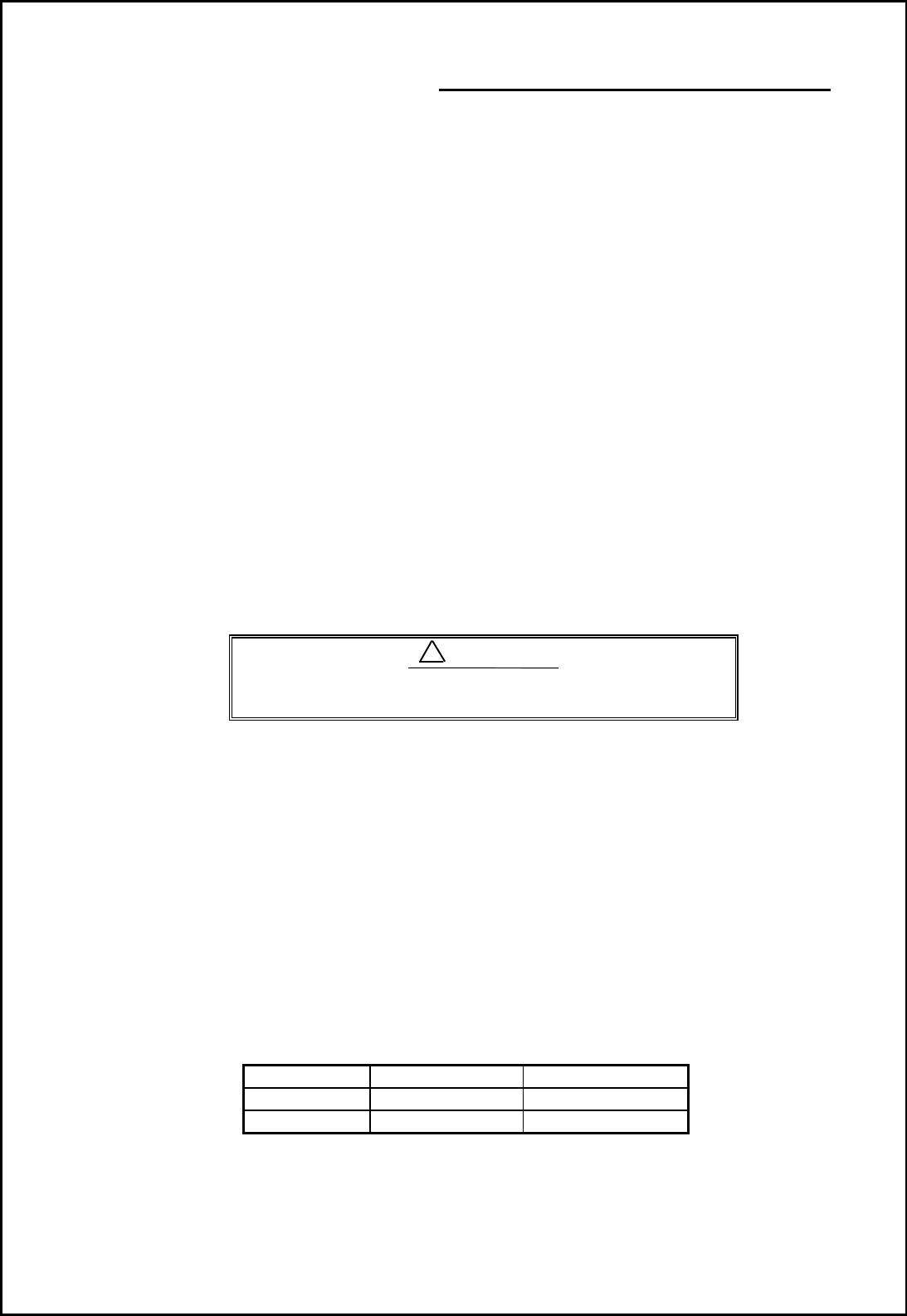
Tab.3-5 Minimum Safe Distance from Magnetic Compass
Standard compass
Steering compass
Scanner unit
2.0m 1.4m
Display unit
2.0m 1.4m
!
CAUTION
12 RA51/52/53/54/55 INSTRUCTION MANUAL – 05
3.3.3 Shifting away from obstacles
• Shifting from keel line
By shifting the scanner position from the keel line to the starboard side of the boat, it is
possible to move shadow zones to the port side. This makes it possible to keep a clear view
to the bow. The distance to be shifted can calculated using the following equation:
Ls=0.4R+D/2 [m] (when R<15m)
Ls=0.025R+D/2 [m] (when R>=15m)
where Ls = distance to be shifted from keel line
D = diameter of obstacle on keel line
R = distance from scanner to obstacle
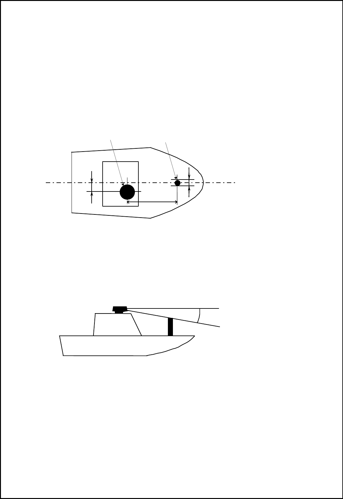
Fig.3-1 Shifting from keel line
‚ Obtaining sufficient dip angle
Raise the scanner position so that there is a sufficient dip angle θ available between the line
of sight from the scanner to the obstacle and the horizontal line. By raising the dip angle
above 5°, it is possible to prevent mid- and long-distance shadow zones. The radar cannot
detect objects below the line of sight.
Fig.3-2 Obtaining sufficient dip angle
Ls
R
D
Scanner Unit Obstacle
Keel line
Horizontal line
Line of sight
θ
RA51/52/53/54/55 INSTRUCTION MANUAL – 05 13
3.4 Installing Scanner Unit _________________________________
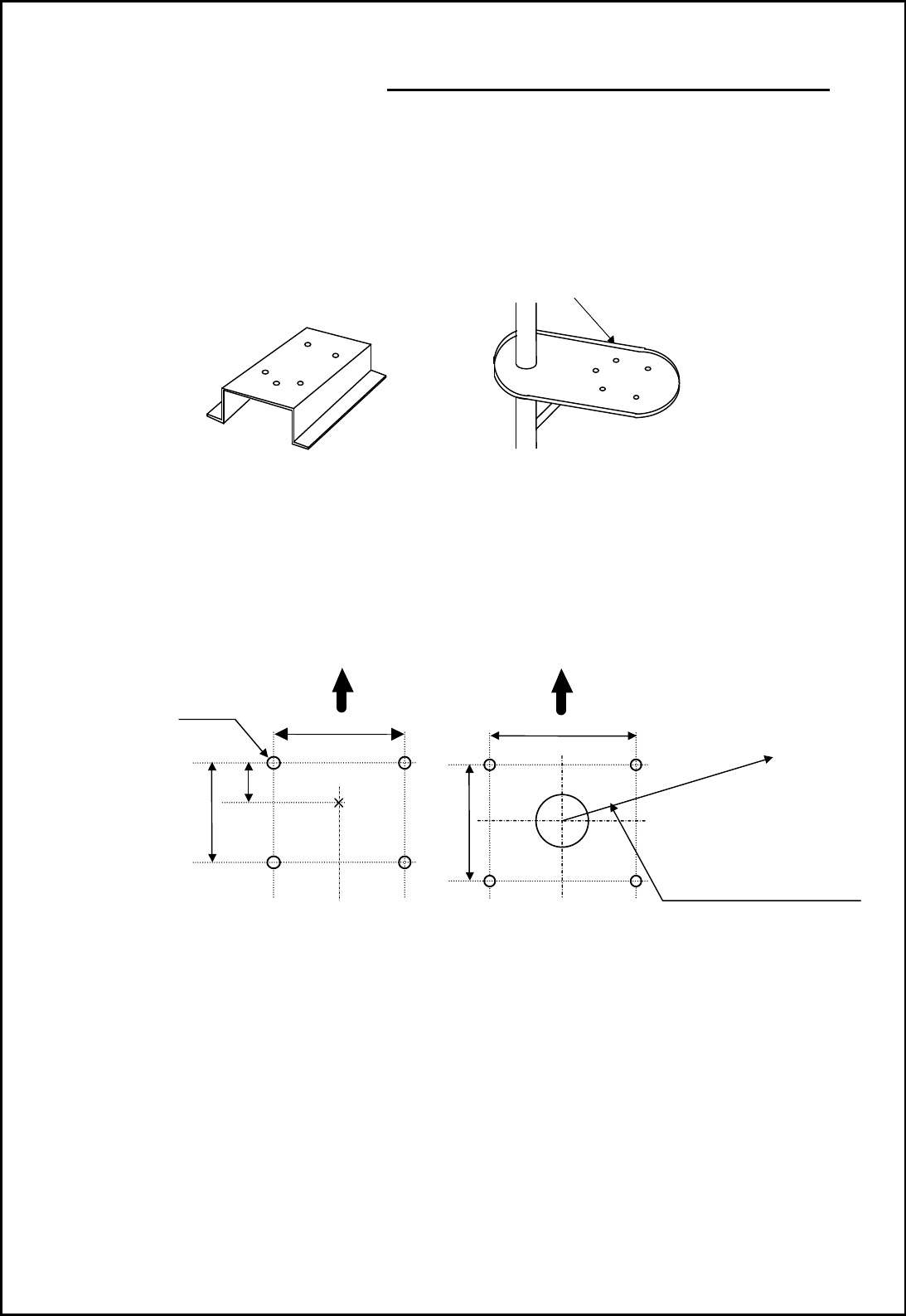
Use a mounting base such as the ones shown in Fig. 3.3, or you can install the scanner directly
to a roof or other flat surface. Be certain you keep the water drain tube clear. It's located at
the bottom of the scanner unit.
Note : If the mounting bracket or surface has a curvature of more than 2mm, use spacers with the
mounting bolts to prevent stress on the scanner housing.
Fig.3-3 Mount base
Use the template provided with this manual to drill five holes for mounting the scanner. At-
tach the four bolts and feed the drain tube through the fifth hole. The bolts included with your
unit will suffice for mount base thickness of 9 to 14 mm (0.35 to 0.55 in.). If the mount base is
thicker or thinner, refer to Tab.3-6. Use a silicone sealant to prevent the bolts from working
loose. The housing may be damaged if you use a thread-locking compound.
Fig.3-4 Hole positions for mounting scanner
Do not use an edge that might trap
water.
Center
214
170
12
φ
×
5
Unit:mm
65
Forward
(8.43 in.)
(2.56 in.)
(0.47 in.)
(6.69 in.)
199
(7.83 in.)
Forward
185
(7.28 in.)
Rotation Radius
R550 (3 ft antenna)
R700 (4 ft antenna)
R1000 (6 ft antenna)
R1400 (9 ft antenna)
RA51 Radome scanner
RA52/53/54/55 Open scanner
14 RA51/52/53/54/55 INSTRUCTION MANUAL – 05
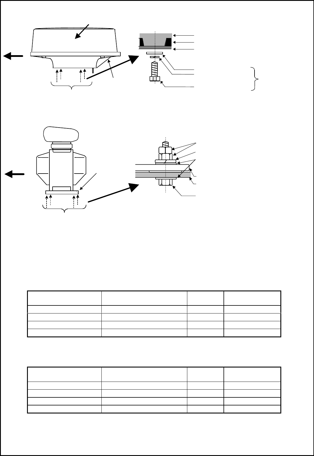
Fig.3-5 Mounting the Scanner
Tab.3-6 Bolts for Mounting Scanner Unit (Radome scanner)
Tab.3-6-1 Bolts for Mounting Scanner Unit (Open scanner)
Thickness of
mount base Bolts necessary to
fix radome scanner Material Remarks
1-4mm(0.04-0.16 in.) M10 × 15 (1.5mm pitch) Stainless
4-9mm(0.16-0.35 in.) M10 × 20 (1.5mm pitch) Stainless
9-14mm(0.35-0.55 in.) M10 × 25 (1.5mm pitch) Stainless Included with radar
14-19mm(0.55-0.75 in.) M10 × 30 (1.5mm pitch) Stainless
Thickness of
mount base Bolts necessary to
fix radome scanner Material Remarks
1-4mm(0.04-0.16 in.) M12 × 45 (1.5mm pitch) Stainless
4-9mm(0.16-0.35 in.) M12 × 50 (1.5mm pitch) Stainless
9-14mm(0.35-0.55 in.) M12 × 55 (1.5mm pitch) Stainless Included with radar
14-19mm(0.55-0.75 in.) M12 × 60 (1.5mm pitch) Stainless
Fix four screws
RA51 Radome scanner
RA52/53/54/55 Open scanner
Fix four screws
Mount base
Washer
Spring washer
M10 Hexagonal bolt
Radome(bottom)
Chassis
Included
Double nuts
Spring washer
Washer
M12 Hexagonal bolt
Mount base
Scanner base
Ship's
heading
Cable inlet
Logo seal on
side wall
Ship's
heading This place
was cut.
Note: See Fig.3-11
RA51/52/53/54/55 INSTRUCTION MANUAL – 05 15
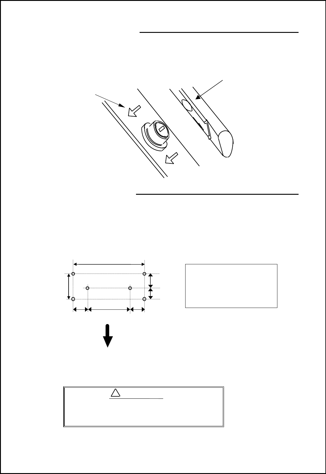
3.5 Installing Antenna Unit _________________________________
Remove the protective cap covering the rotary coupler on the top of the scanner. Match the
antenna radiation direction to direction of the arrow markings on the rotation base and secure
the antenna in position using four M8 bolts.
Antenna radiation surface
Arrow
3.6 Installing Display Unit__________________________________
Choose the proper bolt length according to the thickness of the surface on which you are going
to install the display. Hole size depends on whether you are using self-tapping screws or bolts.
Note : When you install the display by flush mounting to a panel, refer to appendix "OUTLINE
DRAWING". Slide off the four triangular-shaped corner covers, and attach the display unit
to the panel with screws. Replace the corner covers. See APPENDIX.
Fig.3-6 Hole positions for display unit
Do not mount the display where it will be
operating in direct sunlight. The excessive
internal heat buildup may damage the unit.
360
84
Fitting hole
(14.17 in.)
(3.31 in.)
Hole diameter
6mm: Bolts and Nuts
Adequate: Tapping screws
Recommended screw
M5 or equivalent
Unit : mm
47 (1.85 in.)
37 (1.46 in.)
60
(2.36 in.)
240
(9.45 in.)
60
(2.36 in.)
Forward
!
WARNING
16 RA51/52/53/54/55 INSTRUCTION MANUAL – 05
3.7 Connecting Cables _____________________________________
Keep the following tips in mind when laying cables:
- Do not tie the cables for the radar together with cables of other equipment, especially the
power supply cable.
- If you need to pass the cable through a wire chase or conduit, tape the scanner side con-
nector to the wire so it doesn't pull off or get hung up.
- Secure cables in place at intervals of about 40 cm (16").
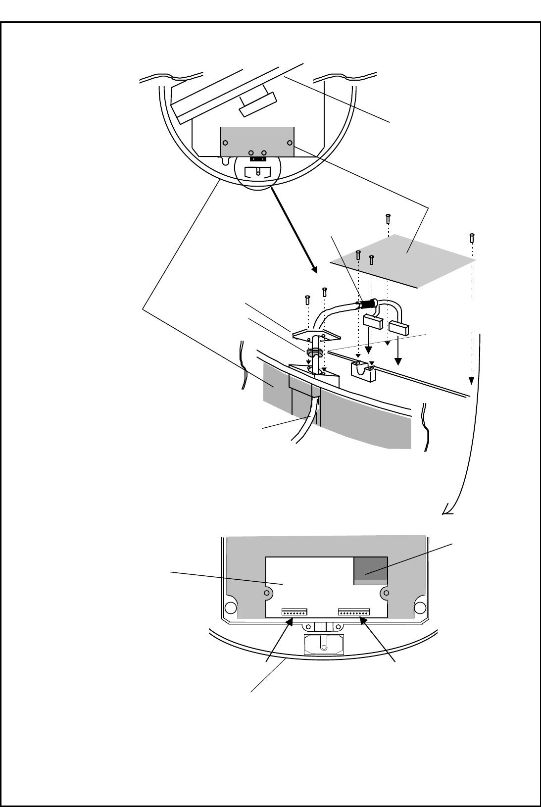
3.7.1 Interconnecting cable (RA51 Radome scanner) (See Fig.3-8-2)
1) Be sure that the power is off. Connect the cable to the plug labeled "SCANNER" on the rear
panel of the display unit. Be sure to secure the rubber boot around the cable connector rim.
2) Remove the upper part of the radome from the scanner unit. Lift it vertically to avoid
bumping it against the antenna. (There are four fixing screws.)
3) Remove the tape securing the antenna.
4) Remove the shield cover located on the backside. (There are four screws.)
5) Remove the cable clamping plate and rubber ring, pass the cable through the opening, re-
place the rubber ring, and clamp the cable to the scanner unit with screws on the fixing
plate. Attach the 7-pin connector to X11 and 9-pin connector to X12 of the printed circuit
board.
6) Replace the aluminum cover. Lay the cable shield into the channel machined into the
aluminum housing. Be careful that the cable will not get caught up between the main unit
and cover.
7) Replace the upper part of the radome being careful not to bump it against the antenna.
Make sure that the cover is positioned in the correct direction as shown in Fig.3-7. The
upper and lower parts of the radome each have four alignment markings indicating screw
positions.
8) Connect the cable to the plug labeled "SCANNER" on the rear panel of the display unit. Be
sure to secure the rubber boot around the cable connector rim.
Ship's
heading
Logo seal on
side wall
Fix four screws
Cable inlet
Fig.3-7 Fitting cover (RA51)
RA51/52/53/54/55 INSTRUCTION MANUAL – 05 17
Fig.3-8 Fitting interconnecting cable (RA51)
Fix connector on
PCB(X11, X12)
Antenna
Stern side Shield cover
Cable shield
Radome (bottom)
Fixing plate
Rubber ring
Interconnecting cable
X12 (Connect here)
Radome (bottom)
PCB
Inner shield
X11 (Connect here)
18 RA51/52/53/54/55 INSTRUCTION MANUAL – 05
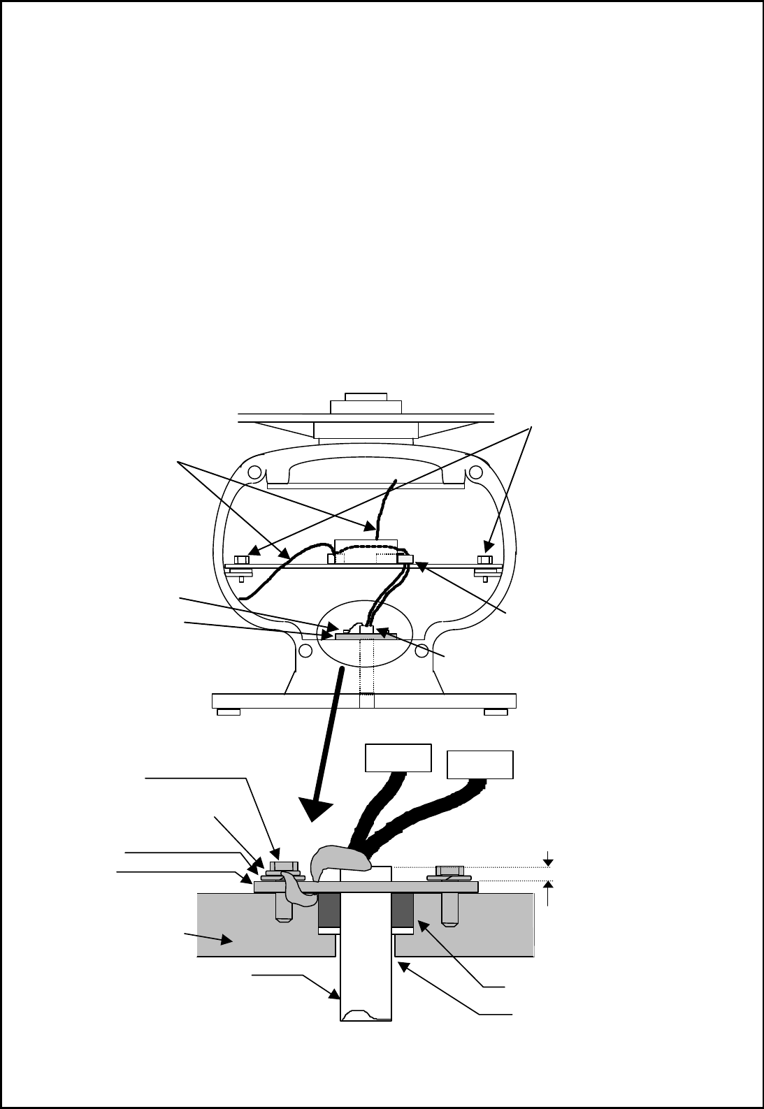
3.7.2 Interconnecting cable (RA52/53/54/55 Open scanner) (See Fig.3-9)
1) Be sure that the power is off. Connect the cable to the plug labeled "SCANNER" on the rear
panel of the display unit. Be sure to secure the rubber boot around the cable connector rim.
2) Use a socket wrench to remove the back cover of scanner unit.
3) Remove the two bolts securing the transceiver.
4) Remove the connectors to the motor (X1:RA52, J5:RA53/54/55) and to the heading switch
(X2:RA52, J3:RA53/54/55). Pull out the transceiver.
5) Remove the four bolts securing the fixing plate at the cable entrance.
6) Remove the metal fixing plate, rubber seal and washer that secure the cable. Pass the
cable through as shown in the diagram below; replace the above items and tighten the
bolts.
7) Return the transceiver to its original position and secure it with the bolts you removed.
8) Connect the 7-pin connector to X11 (RA52)/J1 (RA53/54/55) and the 9-pin connector to X12
(RA52)/J2 (RA53/54/55) of the printed circuit board and connect the two connectors that
you removed in Step 3).
9) Reattach the scanner cover. Take care not to pinch the cable when reattaching the cover.
10) Connect the cable to the plug labeled "SCANNER" on the rear panel of the display unit. Be
sure to secure the rubber boot around the cable connector rim.
TR unit fixing bolts
Remove connector
Fixing bolt
Fixing plate
Inter-connection cable
Clamp
MAX 5 mm
Fixing bolt
Cable shielding terminal
Washer
Fixing plate
Scanner unit
Inter
-
connection cable
Sealing rubber
Cable inlet
When covered with heat-sink tube,
remove any heat-shrink tube.
Lay the braid under the fixing
plate in short length as possible.
RA51/52/53/54/55 INSTRUCTION MANUAL – 05 19
Fig.3-9 Fitting interconnecting cable
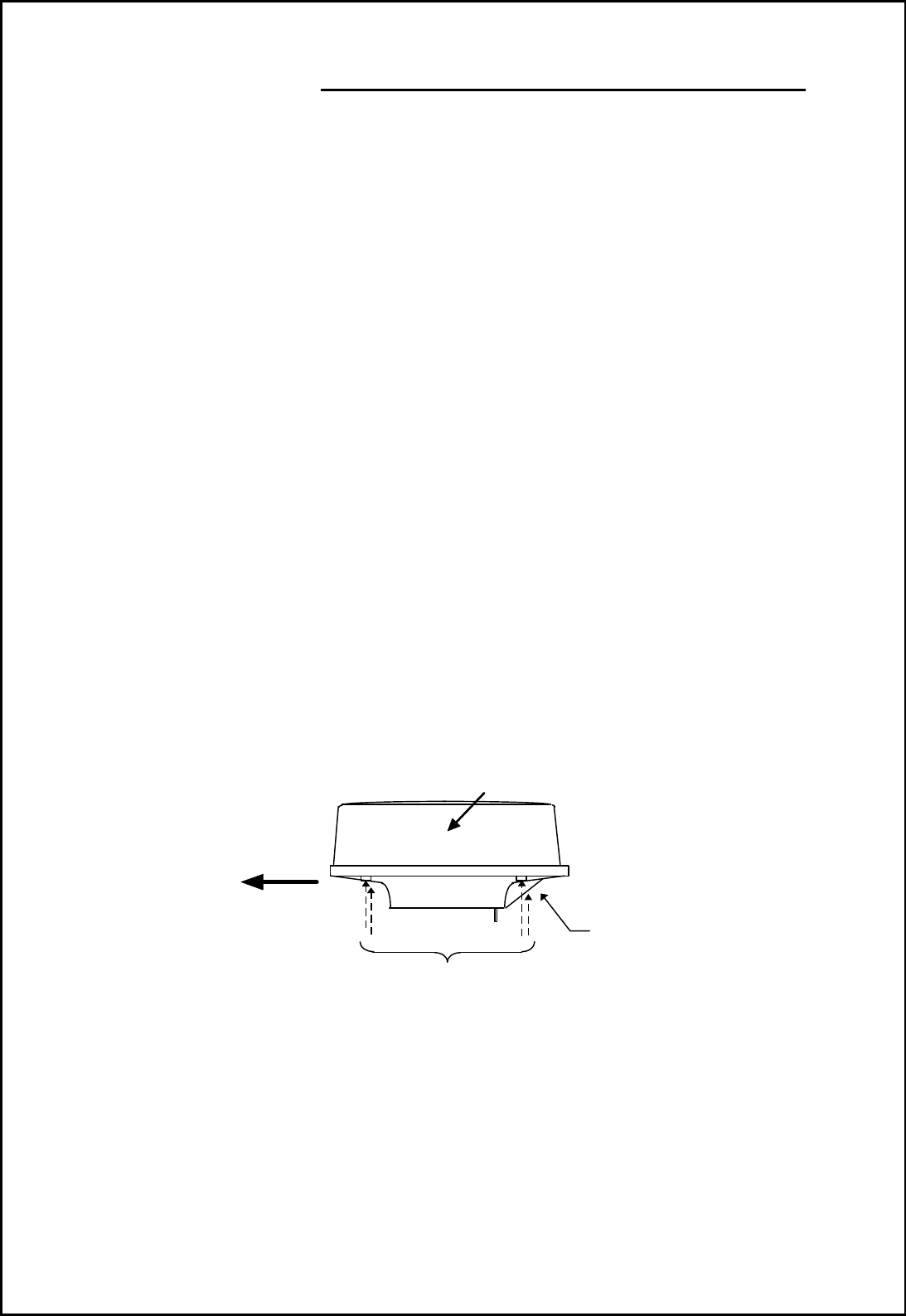
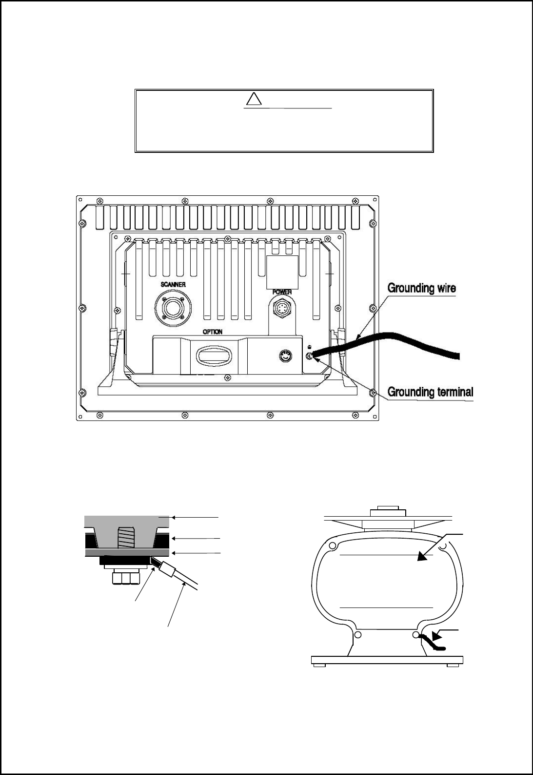
3.7.3 Grounding wire
Connect all grounding wires before connecting the
power supply cable to prevent a shock hazard from
leakage current.
Connect a wire from the grounding terminal on the rear panel of the display unit to your boat's
bonding system or electrical ground bus.
Fig.3-10 Grounding display unit to earth
Connect a grounding wire from one of the bolts on the scanner base as shown in Fig.3-11.
(The crimp terminal and grounding wire is user supplied.)
Fig.3-11 Grounding scanner unit to earth
!
WARNING
Mount
base
Radome(bottom)
Chassis
→
To ship's hull
Crimp terminal
Grounding wire
Radome scanner
Grounding wire
→
To ship’s hull
Scanner cover
Open scanner
20 RA51/52/53/54/55 INSTRUCTION MANUAL – 05
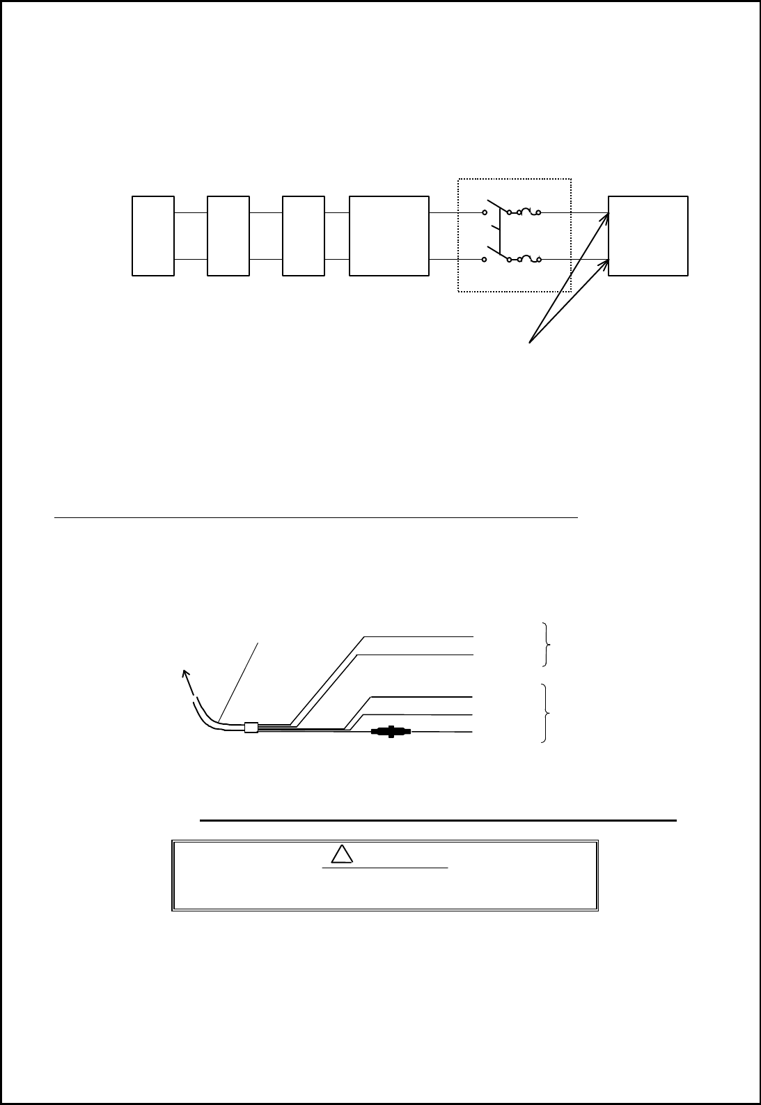
3.7.4 Power supply cable
Power should be fed through a switch and protective fuses (or circuit breakers), as shown be-
low.
WARNING: Do not apply over 41.6V to the unit
or it may be damaged.
Plug the power supply cable into the connector labeled "POWER" on the rear panel of the
display unit. If you don not connect your radar to external equipment, tape the ends of the red
and green wires. Be certain to locate the fuse where it will be kept dry.
When extending the power supply cable, size the wire as follows:
Boat Power Voltage Cable conductor Cable max. length
cross section
12Vdc 10 AWG (3.5 mm2) 3 m
8 AWG (6.0 mm2) 5 m
24Vdc 12 AWG (2.0 mm2) 6 m
10 AWG (3.5 mm2) 10 m
Fig.3-12 Power supply cable
3.8 Adjustment ___________________________________________
Be sure to make the following adjustments. If not
the radar will not display a true image.
When you have finished installing the scanner and display units, turn on the power to see if
they operate. Then make adjustments as detailed below:
• TUNING Refer to Adjusting tuning circuit in 5.5.4.6.5
‚ HEADING DIRECTION Refer to Adjusting angle in 5.5.4.6.5
ƒ DISTANCE Refer to adjusting distance in 5.5.4.6.5
!
CAUTION
Generator
Switchboard
Charger
Storage
Battery
12/24V
Main switch panel
(Knife Switch with Fuses)
Radar Display
Unit
DC voltage
reference points
White
Black
Gray
Green
Red
Power supply cable
To display unit
DC+
DC-
Ground
NMEA (B)
NMEA (A) To external equipment
To power supply
RA51/52/53/54/55 INSTRUCTION MANUAL – 05 21
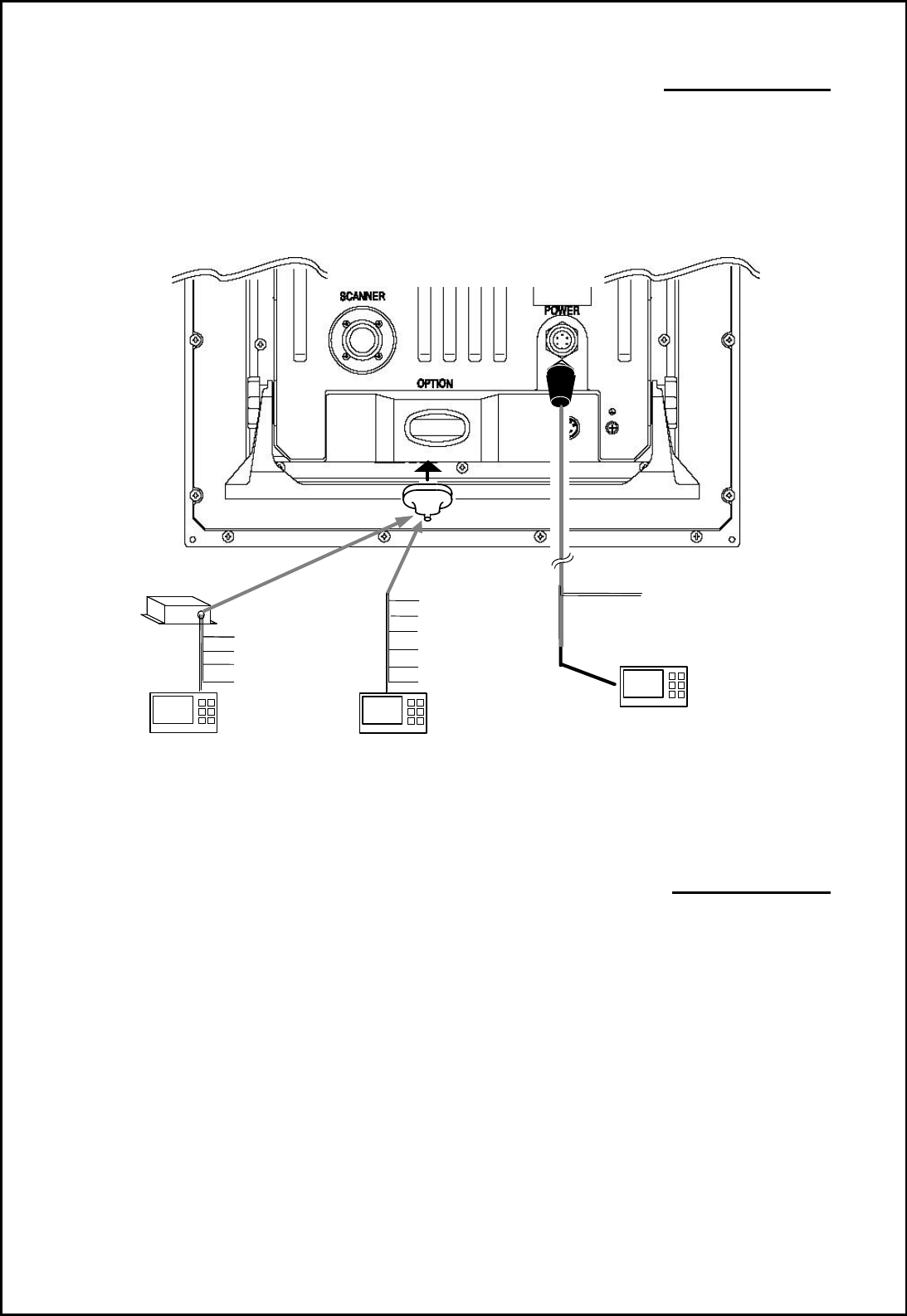
3.9 Connecting External Equipment to Display Unit ____________
The display unit has connections for two NMEA interface ports. One is made through the
power cable. The other is accessed through the OPTION connector on the display's rear
panel. A separate cable and optional junction box are needed to use this interface. (Refer to
CHAPTER 8 (4) External interface.)
Note: SIN/COS and MOB/TARGET signals cannot be accessed through the junction box interface.
Junction box with OPTION cable (Order No. RZ704A)
Fig.3-13 Connecting external equipment to display unit
3.10 Countermeasure for Electromagnetic Interference ___________
The RA51/52/53/54/55 radar uses internal shields and shielded cable to minimize elec-
tro-magnetic interference (EMI). However, when the unit is placed close to a radio trans-
ceiver and either piece of equipment is not properly grounded, the radar will cause inter-
ference.
Here are some hints on how to reduce EMI due to radar.
(1) Installation Location
The display unit, scanner unit and interconnecting cable should be located as far as possible
from the transceiver, antenna cable and antenna of the radio. Experiment with various posi-
tions of both to see if it improves the condition.
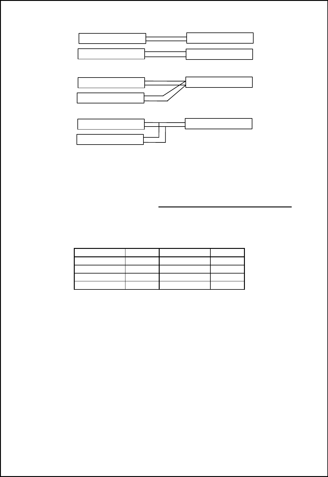
(2) Laying Power Supply Cables
The best solution is to run separate power wires from each unit directly to the boat's electrical
supply source. A connection should be made at the main breaker panel or as close to the
generator or battery as possible. Connection A and B are recommended. Connection C should
not be used.
OPTION connector
(249J153058)
Junction box*note
(RZ704A)
POWER cable
External NMEA equipment
(GPS,LORAN,etc.)
External NMEA equipment
(GPS,LORAN,etc.)
Red :NMEA (A)
Green :NMEA (B)
To power supply
Other radar,
slave monitor,
External buzzer,
Gyro I/F
Other radar,
slave monitor,
External buzzer,
Gyro I/F,
SIN/COS.
MOB(NMEA out)
External NMEA equipment
(GPS,LORAN,etc.)
22 RA51/52/53/54/55 INSTRUCTION MANUAL – 05
Connection A
(Very Good)
Connection B
(Good)
Connection C
(Bad)
(3) Grounding
Both the display unit and the scanner should be securely grounded to the closest point of the
boat's bonding system or electrical ground bus using braided copper wire or copper strap.
3.11 When Discarding Your Radar ____________________________
Tab.3-7 lists the primary component materials of the RA51/52/53/54 radar. Dispose of them
according to local environmental and recycling regulations.
Tab.3-7 Component Materials
Scanner unit Material
Display unit Material
Radome AES Front panel ABS
Chassis A5052P
Rear panel ADC12
Base ADC12 Pedestal ABS+PC
Antenna A5052P
RADAR
RADIO EQUIPMENT
SHIP'S SUPPLY
SHIP'S SUPPLY
RADAR
RADIO EQUIPMENT
SHIP'S SUPPLY
RADAR
RADIO EQUIPMENT
SHIP'S SUPPLY